 A dark quencher genetically encodable voltage indicator (dqGEVI) exhibits high fidelity and speed
Proceedings of the National Academy of Sciences of the United States of America


Edited by György Buzsáki, New York University Langone Medical Center, New York, NY, and approved January 6, 2021 (received for review October 2, 2020)
Author contributions: G.C.F. and I.M. designed research; T.C.A., M.P., L.P., B.S., and I.M. performed research; T.C.A., M.P., L.P., G.C.F., and I.M. analyzed data; and T.C.A., B.S., and I.M. wrote the paper.
1Deceased September 26, 2016.
2M.P., L.P., and B.S. contributed equally to this work.

- Altmetric
Voltage sensing with genetically expressed optical probes is highly desirable for large-scale recordings of neuronal activity and detection of localized voltage signals in single neurons. Here we describe a method for a two-component (hybrid) genetically encodable fluorescent voltage sensing in neurons. The approach uses a glycosylphosphatidylinositol-tagged fluorescent protein (enhanced green fluorescent protein) that ensures the fluorescence to be specifically confined to the outside of the plasma membrane and D3, a voltage-dependent quencher. Previous hybrid genetically encoded voltage sensing approaches relied on a single quenching molecule, dipycrilamine (DPA), which is toxic, increases membrane capacitance, interferes with neurotransmitters, and is explosive. Our method uses a nontoxic and nonexplosive compound that performs better than DPA in all aspects of fluorescent voltage sensing.
Voltage sensing with genetically expressed optical probes is highly desirable for large-scale recordings of neuronal activity and detection of localized voltage signals in single neurons. Most genetically encodable voltage indicators (GEVI) have drawbacks including slow response, low fluorescence, or excessive bleaching. Here we present a dark quencher GEVI approach (dqGEVI) using a Förster resonance energy transfer pair between a fluorophore glycosylphosphatidylinositol–enhanced green fluorescent protein (GPI-eGFP) on the outer surface of the neuronal membrane and an azo-benzene dye quencher (D3) that rapidly moves in the membrane driven by voltage. In contrast to previous probes, the sensor has a single photon bleaching time constant of ∼40 min, has a high temporal resolution and fidelity for detecting action potential firing at 100 Hz, resolves membrane de- and hyperpolarizations of a few millivolts, and has negligible effects on passive membrane properties or synaptic events. The dqGEVI approach should be a valuable tool for optical recordings of subcellular or population membrane potential changes in nerve cells.
The most widely used genetically encodable indicators of neuronal activity are Ca2+-binding proteins that change fluorescence upon binding Ca2+ after it enters through voltage-gated Ca2+ channels. However, these genetically encodable Ca2+ indicators are not ideally suited for accurate detection of single action potentials (APs) and are unable to record membrane hyperpolarizations or depolarizations below AP threshold (1, 2). In contrast, direct optical voltage sensing using genetically expressed probes is highly promising for large-scale recordings of neuronal activity. Many of the various genetically encodable voltage indicators (GEVIs) currently in use were subject to several recent reviews and comparative studies (3456789–10) observing the rapid development of these valuable probes together with highly sensitive fluorescent probes for membrane voltage monitoring that are not genetically encoded (11).
One of the most promising starting approaches has been to fuse the voltage sensor of the Acetabularia chemigenetiacetabulum rhodopsin (Ace2N) and the fluorescent protein mNeonGreen to enable voltage-sensitive Förster resonance energy transfer (FRET) (12). This sensor has been shown to work in expression systems, neurons in culture, slices, in the intact brains of awake mice, and in dendrites of olfactory neurons in intact flies. Since then, several other approaches have been developed (1314–15) that work well for determining cell-specific behavioral correlates in mice. The development of the Optopatch3 mouse line (13) was a revolutionary milestone in advancing research using GEVIs. The most recent advances in the field combine a voltage-sensitive microbial rhodopsin with a self-labeling protein domain that covalently binds the synthetic Janelia Fluor fluorophore that has to be administered separately. The degree of FRET is modulated by the voltage-sensitive absorption spectrum of the rhodopsin. This type of GEVI has been termed chemigenetic as it has a chemical and a genetic component. Voltron (16) and its latest derivative, Positron (17), have been used in various expression systems including intact mouse brains. Another chemigenetic fluorescent voltage sensing approach, also called hybrid GEVI, is based on FRET, or rather quenching (18) between two components, but the voltage sensor is not genetically encoded. A fluorescent particle is anchored to one side of the membrane and a small lipophilic anion (dark quencher) is used as the voltage sensor that is rapidly moved inside the membrane by the electric field. The approach was pioneered over 20 y ago (19) and has been refined by using the FRET reaction between a stationary fluorescent lipid and a mobile dye, which gave an astonishing >50% fluorescence change per 100 mV with a time constant of <0.4 ms (20). The principle was turned into a genuine GEVI approach by using a genetically encodable membrane-targeted fluorescent protein as the membrane-anchored fluorophore (usually myristoylated and palmtoylated at Gly and Cys residues), and dipicrylamine (DPA) as its FRET quencher pair (21). DPA was known from early charge-pulse relaxation experiments to electrophorese through lipid membranes with a submillisecond translocation rate (22) that was as fast as gating currents in the squid axon (23). When used in combination with the lipophilic fluorescent dye DiO, that had to be fastidiously loaded into individual neurons, DPA gave very fast and large optical voltage signals (2425–26). As the DPA absorption and enhanced green fluorescent protein (eGFP) emission spectra do not greatly overlap (SI Appendix, Fig. S1A), improvements in the method have been attained by using the blue-shifted enhanced cyan fluorescent protein (18), by developing a membrane localized fluorophore (hVOS 1.5, a cerulean fluorescent protein tagged at its C terminus with a truncated farnesylation motif) (27), and by proposing various optimizations of the approach (28).
In general, this two-component approach provides good signal-to-noise ratio (SNR) for the detection of APs and for recording subthreshold synaptic events in various preparations (21, 2930–31), but in all of these studies the voltage-dependent dark quencher remained the same: DPA. While this molecule satisfies many of the original requirements (19) for voltage sensing, it also has several drawbacks. These include its accumulation on the outer surface of the membrane below approximately −50 mV, thus making it difficult to report small membrane hyperpolarizatios (29), the considerable capacitive membrane load near the required concentrations for voltage sensing (21, 28, 32) that causes time-dependent deterioration of APs (26), and its interactions with various neurotransmitter systems (3334–35). In addition, as it is made up of two trinitrotoluene molecules joined together, DPA (also known as hexanitrodiphenylamine, or HND) is highly explosive; indeed, it was actively used as an explosive in World War II.
In order to replace DPA in the two-component GEVI approach we have set out to carry out a systematic search for different dark quenching molecules. After testing several dozens of compounds, we identified an organic nitroazobenzene dye (Disperse Orange 3 or 4-amino-4′-nitroazobenzene, CAS number 730-40-5, herein referred to as D3) with an absorption spectrum better suited than DPA to quench eGFP fluorescence (SI Appendix, Fig. S1A). Importantly, as a dark quencher D3 does not have any autofluorescence, and therefore, despite being a voltage indicator, it does not report a fluorescence signal by itself. Here we report on the superior properties of the dark quencher D3 in combination with eGFP for a dark quencher GEVI (dqGEVI) approach with the fluorophore anchored to the outside of the membrane by the glycosylphosphatidylinositol (GPI) motif (36) (GPI-eGFP; SI Appendix, Fig. S1B) in neuronal cultures and demonstrate its innocuous effects on passive membrane properties and synaptic events. Some GEVIs are quite adequate for 2P imaging (3738–39), and our approach should also perform well in this mode, as 2P fluorescent voltage measurements have been very successful with another quencher (DPA) paired with a nongenetically encoded membrane fluorophore (25, 26). We have compared the speed of our voltage sensor to one of the GEVIs used for 2P imaging, ASAP2s (37), and find a considerable faster fluorescence response during APs.
Results
Fast, High-Fidelity Reporting of AP Firing and Membrane Hyperpolarizations.
We have recorded from mouse and rat cortical and hippocampal neurons in culture that were transduced with the GPI-eGFP construct carrying recombinant adeno-associated viruses. The neurons expressed the fluorophore in their membranes including their somata, dendrites, and axons even as long as 6 wk after viral transduction (SI Appendix, Fig. S1C). In our recordings we typically used neurons after 2 to 3 wk of viral transduction. Simultaneous whole-cell patch-clamp recordings and optical recordings were done at 32 ± 1 °C starting at ∼5 min following addition of 2 to 10 μM D3. Several of our recordings persisted for >60 min, which allowed us to determine the lasting presence of D3 in the membrane following its washout that lasted at least 48 h (discussed below). Most recorded neurons were subjected to a standardized current injection protocol consisting of eight 300-ms-duration current injections (staircased as three hyperpolarizing and five depolarizing pulses, usually ranging between −200 and +300 pA, in steps set to provide −30 to −40 mV initial hyperpolarizations from the resting membrane potential (RMP) of −60 to −68 mV and AP firing upon depolarizations). Such an experiment is shown in Fig. 1 with the optical recording sampled at 1.08 kHz and the electrical recording sampled at 50 kHz. Note that in addition to the accurate detection of APs (Fig. 1 A and D–H), small hyperpolarizations were also truthfully detected by the dqGEVI (Fig. 1 B–D and F). In this particular cell, the SNR (z-score equivalent) (29) of the first AP in the train was 31.4. The mean (± SEM) fluorescence change (ΔF/F) of the 27 APs in this recording was 5.01 ± 0.05%. Cohen’s d statistic for the same 27 APs was 288.3 when the SD of a 200-ms baseline was considered for the analysis. However, since the pooled SD (Materials and Methods) is reduced by the large number of points present in a long baseline, we also calculated the d values using 27 baseline points to match that of the APs. In this case, the d values ranged between 103.0 and 112.3 for 12 randomly selected baselines, an outstanding statistical effect size (40). Remarkably, in a total of 24 neurons the average SNR (z-score equivalent), calculated from unsmoothed single fluorescence traces of the first APs evoked by the injected current, was 17.95 ± 1.12 (mean ± SEM; n = 24).

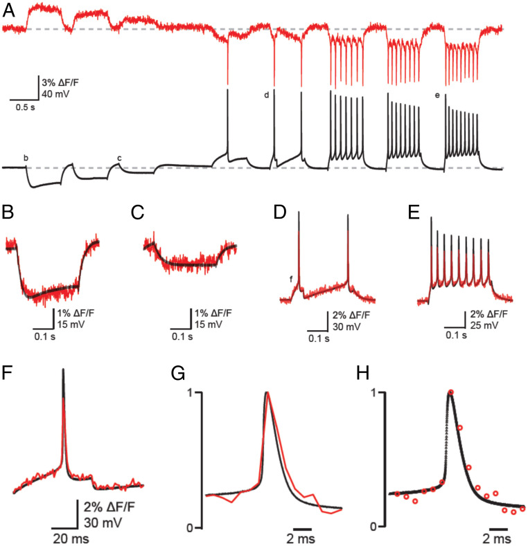
Simultaneous optical and electrical recordings of membrane potential changes in a cultured neuron using the dqGEVI approach with 10 μM D3. (A) Single continuous traces of optical recordings (red) without image processing or filtering, as sampled at 1.08 kHz with an EM-CCD camera. The patch-clamp recordings in the I-clamp configuration (black) were sampled at 50 kHz. Various current pulses of 300-ms duration were injected into the neuron to produce hyper- and depolarizations of the membrane and AP firing. The average ΔF/F (± SEM) for the 27 APs depicted in this trace was 5.01 ± 0.05%. Horizontal dashed line indicates the RMP of −65 mV. (B–E) Parts of the traces labeled with the respective letters on panel A are shown in enlarged snapshots as superimposed traces of optical (red) and electrical (black) recordings. Note the highly accurate temporal overlap between the fluorescence and membrane potential changes. (F) Overlay of fluorescence (red) and membrane voltage (black) during an AP at higher temporal resolution. Note the superimposition of the two traces during both the pre-AP voltage rising to threshold and during the post-AP hyperpolarization. (G) Fluorescence and membrane potential are shown normalized to the peak of the AP. (H) The sampling data points are shown for the two recording modalities to illustrate the rapid change in fluorescence despite the relatively low sampling frequency.
The standardized current protocol experiments also allowed us to correlate the membrane potential (Vm) changes measured by electrophysiology with the fluorescence changes (ΔF/F) as measured by the mean gray levels in the regions of interest (ROIs) (usually the somatic membrane). For these measurements the electrophysiology traces were downsampled to match the sampling of the fluorescence (∼1.08 or 2.225 kHz) (Fig. 2 A and B). In this manner, the two traces could be plotted against each other to obtain the graph of ΔF/F as a function of the membrane potential through a point-by-point correspondence. The slope of the line fitted to the ∼3,000 to 6,000 point pairs in each cell yielded the ΔF/F for a Vm change of 100 mV (Fig. 3C). In n = 10 cells, under matching experimental conditions, except for the sampling rate of the fluorescence, the average ΔF/F for a 100-mV change was 6.604 ± 0.421% (± SEM). In all cases, the responses were consistently linear in the Vm range of −100 mV to +40 mV.
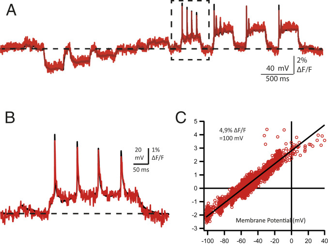
Calculation of the correspondence between ΔF/F and membrane potential. (A) A current injection protocol similar to that used in Fig. 1 in another cultured neuron expressing GPI-eGFP recorded in the presence of 10 μM D3. Superimposed traces of nonimage processed fluorescence sampled at 1.08 kHz (red) and the I-clamped membrane voltage (black) downsampled to the same sampling interval from the original 50 kHz. The horizontal dashed line indicates the RMP of −60 mV. (B) A portion of the traces is shown from the part enclosed in the dashed lined box of A. Note the excellent overlay between the optical and electrical recordings as indicated by the accurate reporting of the decreasing AP amplitudes during the train, and the subthreshold depolarizing events (∼5 mV) prior to the current injection (probably spontaneous excitatory postsynaptic potentials; arrowhead) of <10 mV amplitudes. (C) The relationship between ΔF/F and membrane potential was calculated by plotting the two traces point-by-point against each other. The slope of the linear regression (black line) yields the relationship for this cell as indicated in the inset.
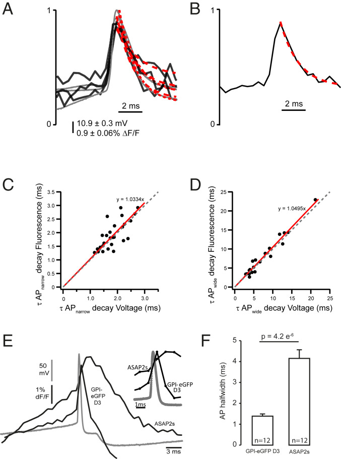
Speed of the dqGEVI approach as measured during the decay of APs. (A) Rapidly decaying APs (usually those early on during a current pulse injection) were normalized to their peaks (gray: electrophysiology; black: fluorescence) and single exponentials were fitted to their decay phases (dotted red lines). (B) The same was done for slower APs (usually recorded during the late phases of the depolarizing current injections). (C) Comparison of the fast AP decays show a remarkable one-to-one correspondence between the optical and the electrical measurements (dotted line with a slope = 1 for comparison; red line is the linear fit to the data; slope = 1.0334 ± 0.0366; R2 = 0.746). (D) Similar to C but for the APs with slower decays (slope = 1.0495 ± 0.026; R2 = 0.939). Values expressed as mean ± SD. (E) AP waveforms recorded in HEK293T cells transfected with ASAP2s and GPI-eGFP D3 in voltage clamp mode. Optical traces (black) show the average of 12 traces from 12 cells. The AP waveform voltage trace is indicated in gray. (Inset) The lower sampling rate (1 kHz) of the fluorescent traces makes it look as if the upswing on the AP voltage trace is delayed, which is not the case. (F) Comparison of AP width of the optical traces measured at 50% amplitude. Significance was assessed by Wilcoxon rank-sum test.
Fluorescence Signals Using D3 dqGEVI Detect Rapid Changes in Vm Associated with APs.
The relatively low maximal sampling rate of the fluorescent signals with our electron-multiplying charge-coupled device (EM-CCD) camera (∼2.2 kHz) precluded accurate measurements of the rising phase of APs or fitting exponential functions to the rising phases of square-shaped voltage pulses. Therefore, we decided to compare fluorescent and electrical measurements of fast changes in Vm by measuring the decay time constants (τ) of APs where more sample points were available in the fluorescence traces. We divided the APs into two groups: the rapidly decaying APs, usually those that were elicited first in a train of spikes, and slowly decaying APs, that is, those that were the last in the train when due to various biophysical factors the recovery of the membrane potential following an AP is hindered. In these experiments the APs recorded by fluorescence (sampled at ∼2.2 kHz) or through electrophysiology (sampled at 50 kHz) were normalized to their peaks and single exponentials were fitted to the decay phases (Fig. 3 A and B). Comparison of the fast AP decays shown nearly one-to-one correspondence between the two measurements. In six cells a total of 27 fast APs (τ range: 1 to 3 ms; Fig. 3C) and 20 slow APs (τ range: 3 to 22 ms; Fig. 3D) were compared. The linear fit to the fast AP data has a slope = 1.0334 ± 0.0366 and R2 = 0.746 (Fig. 3C), while the linear fit to the slower decaying APs has a slope = 1.0495 ± 0.026 and R2 = 0.939 (Fig. 3D). The high correlation between the τs indicates the accurate and fast rendition of membrane potential changes by the D3-GPI-eGFP dqGEVI. We also compared the performance of our dqGEVI approach with that of another GEVI, ASAP2s. The D3-GPI-eGFP dqGEVI fluorescence followed with much higher fidelity the electrophysiological AP waveform than the fluorescent signal generated by ASAP2s (Fig. 3E). The summary data show the AP half-width measurements that were obtained by the two approaches, indicating a significantly faster measurement with the D3 dqGEVI approach (Fig. 3F).
Recordings of Subthreshold Changes in Vm.
We wanted to know how accurately the dqGEVI approach reflects subthreshold changes in Vm. Therefore, we created a stimulus protocol that systematically and reproducibly altered the Vm in voltage-clamped cultured neurons expressing GPI-eGFP. The protocol changed the Vm according to a chirp function (Materials and Methods) that increased from 10 Hz to 100 Hz over 4 s and had a peak-to-peak amplitude of 40 mV (± 20 mV from the RMP). We then carried out extensive analyses of the correlations between the Vm (downsampled to the sampling rate of the fluorescence) and the ΔF/F over the 4 s of the chirp pulse of increasing frequency. Fig. 4A shows such an experiment together with the Morlet wavelet transforms of the two signals (ΔF/F and Vm). Using the Hilbert transform (Materials and Methods) we also calculated the phases of the two responses (Fig. 4 B and C) during the duration of the 4-s chirp wave. For each experiment we plotted the point-by-point correlation between the phase of the ΔF/F and the phase of the Vm signals. These plots were binned in three-dimensional histograms (Fig. 4D), and Pearson’s R value was calculated, together with its significance based on the t distribution of R/SQRT[(1 − R^2)/(N − 2)], where N is the number of point pairs. Furthermore, we calculated the cross-correlation between the phase of ΔF/F and that of Vm (Fig. 4E). The values of the cross-correlations were normalized using the root-mean-square (RMS) values of each signal (Materials and Methods). Finally, for each experiment we subtracted the phase of the Vm signal from the ΔF/F phase in a point-by-point manner. The values of the subtracted points were binned at 0.1 rad, and a histogram was generated for each experiment. We then fitted a Gaussian to the histogram (Fig. 4F) that provided the mean difference between the two phases (in rad). A negative value of the difference indicates that the phase of the ΔF/F lags behind that of the Vm signal. The value of the phase difference expressed in rad was converted to milliseconds using the average frequency over the entire duration of the chirp function (55 Hz, i.e., 2π rad = 18.182 ms). From eight chirp sweeps recorded in six different neurons at their RMP of −68 to −72 mV, the mean (± SEM) values were as follows: R (ΔF/F phase, Vm phase correlation) 0.476 ± 0.056; t value 40.34 ± 6.90; degrees of freedom (range) 4,330 to 8,872; P (range) 0.00 to 1.92E-67; normalized R (ΔF/F, Vm cross-correlation) 0.596 ± 0.063; degrees of freedom (range) 4,330 to 8,872; P (range) 0.00 to 5.27E-122; average (ΔF/F phase – Vm phase) in rad: −0.0097 ± 0.0084, in microseconds: −276 ± 240. Taken together, our measurements indicate that the dqGEVI approach highly accurately reflects slow (10 Hz) and fast (100 Hz) subthreshold changes in Vm.
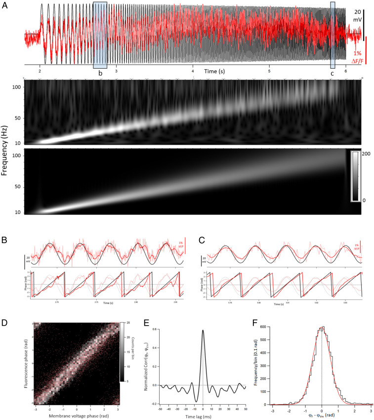
Amplitude and phase correspondence between ΔF/F and Vm during subthreshold stimuli of increasing frequencies. (A) Superimposed plots of the ΔF/F (red) and Vm (black) during a 4-s chirp pulse (10 to 100 Hz). Morlet wavelet transforms of the ΔF/F trace (Top) and of the Vm trace (Bottom) showing the linearly increasing frequency responses. Note how the ΔF/F response faithfully follows the linear change in frequency. (B and C) Zoomed images of the ΔF/F and Vm traces from the shaded boxes labeled in A. (Top) The smoothed ΔF/F (dark red) and raw ΔF/F (light red) traces, superimposed with the Vm trace (black). (Bottom) The phases of the ΔF/F (red) and Vm (black) with the smoothed ΔF/F and Vm traces in the background shown in fainter colors. (D) Plot of ΔF/F phase vs. Vm phase. Individual points are represented in red, and the greyscale represents the binned histogram values with a bin width of 0.04π rad. Pearson’s R = 0.61; P = 0. (E) Normalized cross-correlation between ΔF/F phase and Vm phase. The RMS normalization of the cross-correlogram was done as described in Materials and Methods. (F) Histogram of point-by-point differences between ΔF/F phase and Vm phase. The mean of the Gaussian fit (red) is at −0.011 rad, that is, −311 μs. The mean ± SEM lag betwen ΔF/F phase and Vm phase determined in this manner in eight experiments was −276 ± 240 μs.
Very Slow Single-Photon Photobleaching.
One of the inherent problems of using GEVIs is the rapid photobleaching upon continuous single-photon illumination. The longest of the bleaching time constants for several GEVIs is ∼400 s for QuasAr2 (6), while during two-photon illumination these values are extended by three- to fourfold (6). We measured the single photobleaching time constant of our dqGEVI under 15-min continuous illumination conditions in cultured neurons (Fig. 5A). The decay time constant from five averaged experiments was 2,629.6 s (∼44 min), which compares very favorably to the newly developed two-component GEVIs Voltron (16) and Positron (17), and the SNR measured periodically during the continuous illumination had a similarly slow decay (Fig. 5 B and C).
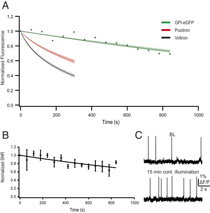
High photostability of GPI-eGFP D3. (A) Normalized fluorescence intensity of GPI-eGFP D3 over 15-min continuous illumination with an LED (illumination intensity 4.3 mW × mm−2, the standard intensity used in all of our experiments). Points are average fluorescence values sampled every 60 s in three cells. The fitted exponential decay (green line) has a time constant of 2,268 s (∼38 min) with a ±SD (shaded green) of 177 s (∼3 min). Graph is superimposed with the photostability curves for Voltron (black) and Positron (red) (17) (illuminated with an LED, light intensity 18 mW × mm−2). (B) Normalized SNRs of GPI-eGFP D3 over 15-min continuous illumination (n = 5 neurons). Error bars indicate ± SEM. (C) Example raw traces from a single cultured neuron showing spontaneous APs at baseline (Upper) and after 15 min of continuous illumination (Lower).
Receiver Operating Characteristic Analyses of Induced AP Firing at 50 Hz and 100 Hz.
During 300-ms-long depolarizing current pulse injections, cultured cortical or hippocampal neurons under our recording conditions did not fire at frequencies of >30 Hz (e.g., Fig. 1E). As previously reported (12) for other GEVI approaches, at these relatively low frequencies there was a one-to-one correspondence between the APs detected in the optical voltage traces and the APs recorded by the patch-clamp method. However, we wanted to know whether the dqGEVI method is also capable of detecting APs elicited at higher frequencies. We injected short (4 ms) high-amplitude (800 to 1,500 pA) current pulses to elicit APs at 50 Hz (Fig. 6 A and B) and at 100 Hz (Fig. 6 C and D) in a highly controlled manner. For these experiments, the ΔF/F traces were smoothed according to the Savitzky–Golay method by a 17-point (for 2.225-kHz sampling) and 7-point (for 1.08-kHz sampling) fourth-order polynomial. The threshold for AP detection in the smoothed ΔF/F traces was set at 75% of the peak amplitude of the first fluorescent AP. Point-to-point correlations between smoothed ΔF/F traces and the Vm traces downsampled to match the fluorescence sampling rates were >0.9 (Fig. 6 B and D). In six neurons each, we performed a binary receiver operating characteristic (ROC) analysis of several sweeps with a total 579 APs and 102 failures elicited at 50 Hz and 396 APs and 296 failures elicited at 100 Hz (Fig. 6E). Such an analysis, primarily used for determining the reliability of a diagnostic test, reveals the accuracy of the applied detection method. However, in contrast to a diagnostic test, where the precise prevalence of the disease in the population is rarely known, in our experiments the Vm recordings provided the true rates of APs and failures elicited by the current pulses, thereby making this a very powerful analytical tool. It should also be noted that the failures are not simply absences of APs but represent quite large subthreshold depolarizations elicited by the short current pulses, thus making the distinction between APs and failures more difficult. The ROC analysis indicates very high levels of sensitivity (50 Hz: 98.8%; 100 Hz: 97.7%) and specificity (50 Hz: 98.0%; 100 Hz: 92.9%) for discriminating between APs and failures at these two frequencies. A valuable statistic is the diagnostic odds ratio (DOR) of the test (41) that represents the ratio of the odds of ΔF/F positivity when APs are present in the Vm trace relative to the odds of ΔF/F positivity when there are AP failures in the Vm. The DOR values were >4,000 (50 Hz) and >500 (100 Hz), while the calculated values for the area under the curve (AUC) were 0.999 (50 Hz) and 0.993 (100 Hz). Such large values of DOR and AUC are indicative of a test of extremely high diagnostic value (41). In addition to the ROC analysis that does not account for consecutive APs, we also calculated the rates of detection of two or more successive APs at 50 Hz and 100 Hz. Of the total of 579 APs elicited at 50 Hz stimulation, 561 were part of bursts of ≥2 APs. Of these, 554 (98.75%) were also detected optically. Of the 396 APs elicited by 100 Hz stimulation 197 occurred in bursts of ≥2 APs. Of these, 193 (97.97%) were also detected optically. As previous studies did not make an effort to induce high-frequency APs but mainly relied on the intrinsic firing rates of the recorded neurons (<40 Hz), the sizeable detection rates by our dqGEVI approach are encouraging for its usefulness to detect APs from rapidly firing cell types such as interneurons. Accordingly, the dqGEVI method is sufficiently sensitive to detect small Vm deflections, yet its dynamic range is adequately large to enable a very simple threshold detection to differentiate between APs and failures.
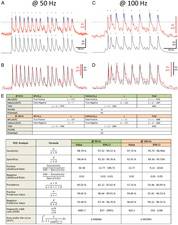
Accuracy of AP detection at 50 Hz and 100 Hz and its ROC analysis. (A) Detection of APs elicited with 4-ms current pulses at 50 Hz. (Upper) Raw (light red) and smoothed (red) ΔF/F signal of example recording. Threshold (dashed line) for detection of fluorescent APs (fAPs) was set at 75% peak amplitude of the first fAP, determined as the peak ΔF/F in a ±3-ms time window of the first electrophysiological (Vm) AP relative to a 180 ms baseline period. Crosses indicate threshold crossings, peaks of detected fAPs are indicated in blue. (Lower) Corresponding electrophysiological trace. Threshold for detection of Vm APs was set at 0 mV. (B) Superimposed raw fluorescent and electrophysiological traces from (A) (R = 0.98). (C) Same as A at 100 Hz. (D) Superimposed raw fluorescent and electrophysiological traces from C (R = 0.95). (E) ROC analysis of the indicated number of cells and traces with 579 APs and 102 failures elicited at 50 Hz and 396 APs and 296 failures elicited at 100 Hz.
Simultaneous Recordings from Two Neurons and from Subcellular Compartments.
GEVIs offer the possibility to record simultaneously from a large number of neurons, thus allowing the monitoring of both subthreshold activities in some cells and AP firing in others. We recorded membrane fluorescence changes with 2 μM D3 after inducing synchronous activity by exposing neuronal cultures for at least 45 min to the K+ channel blocker 4-aminopyridine (4-AP; 50 μM), a compound known for inducing epileptiform bursting activity (42). Usually, we recorded from two neurons within the same field of view (Fig. 7A). One of the two cells also underwent whole-cell recording in I-clamp configuration. Recordings from such an experiment are shown in Fig. 7 B–D. Both electrophysiological and optical recordings of the membrane voltage indicated the presence of subthreshold and suprathreshold activities (Fig. 7 B–D). Similar recordings were obtained in five other cell pairs in different cultures, indicating that simultaneous optical recordings of membrane voltage using the D3 dqGEVI method will be a valuable tool to detect neuronal synchrony and the temporal activation in a synaptically interconnected network. We have also measured the fluorescence in different ROIs recorded in different subcellular compartments. In Fig. 7E we show two dendritic locations that were on average 12.6 μm and 40.6 μm away from the soma. These two dendritic locations received the back-propagating somatic depolarizations elicited by 4-AP with delays proportional to the dendritic distance from the soma (Fig. 7F).
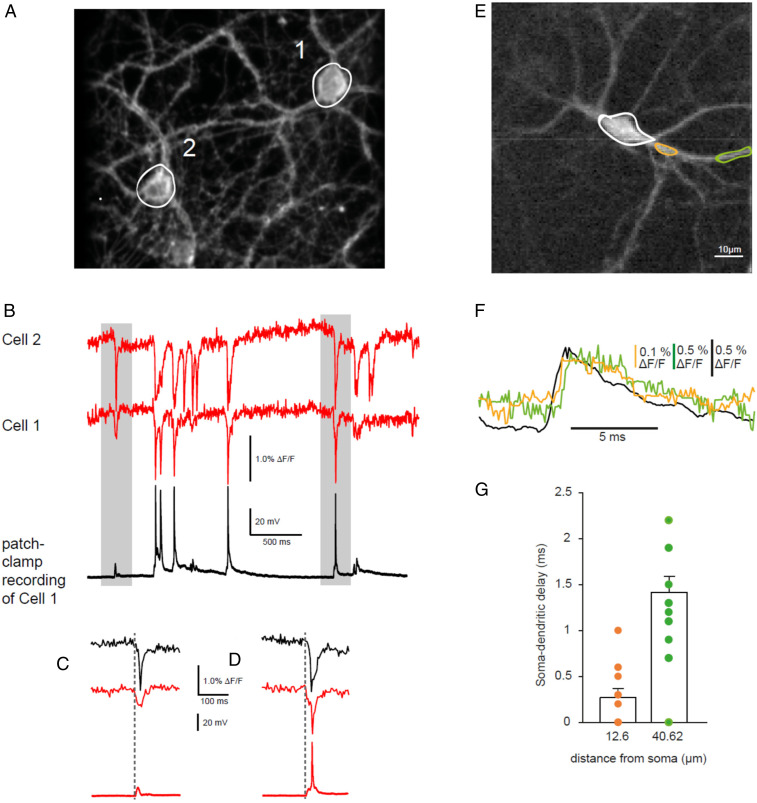
Optical recordings of synchronous activity. (A) Two fluorescent cultured neurons on the same coverslip. Cell 1 was recorded in the I-clamp whole-cell mode. Cell 2 was only optically monitored. White circles indicate the ROI from which the imaging trace was taken. (B) When treated with 4-AP (50 μM) neurons developed epileptiform bursting. The simultaneous recordings show the fluorescent signals in the two cells (red and green traces) and the electrical recording in Cell 1 (black trace). (C) The area shaded in gray on the left of B magnified to show suprathreshold activity in Cell 2 and subthreshold activity in Cell 1. (D) The area shaded in gray on the right of B magnified to show suprathreshold activity in both cells. Note the alignment of the start of the synchronous discharges in both C and D. (E) A 128- × 128-pixel image of a GPI-eGFP–expressing cultured cortical primary mouse neuron imaged at 10 kHz. Spontaneous activity was elicited by incubation with 4-AP. (F) Superimposed single traces of the dendritic signals at a proximal location (orange) and at a more distal location (green). The somatic signal (black, ROI indicated at soma with white circle) precedes the dendritic signals. (G) Quantification of the soma–dendritic delay in a single neuron measured on average at a distance of 12.60 ± 0.09 µm (orange) and 40.62 ± 0.17 µm (green) from the soma (n = 13 depolarizations). Error bars indicate ± SEM.
Recordings after Washout of D3.
The GEVI that uses a single molecule for voltage sensing or the FRET between two fluorescent proteins differ from the dqGEVI approach in that the latter uses a small molecule that first has to be added to the extracellular compartment to eventually partition itself into the membrane. An open question remains whether the small quenching molecule needs to be continuously present in the extracellular space, or whether it is sufficient to load the membrane only once. This question has not been addressed in previous voltage-sensing experiments with DPA, and therefore it is not known if DPA can reside long enough in the cell membrane to allow the optical recordings to persist following its washout from the environment. We have addressed this question with the D3-GPI-eGFP dqGEVI approach. Cells were exposed to 10 μM D3 for 10 min. Subsequently, the cells were perfused with a solution containing no D3 (and no dimethyl sulfoxide [DMSO]) at a flow rate (3 mL/min) that exchanged the recording chamber volume several times a minute. Both optical and electrophysiological recordings were undertaken immediately after washout was started and were continued for as long as 70 min. Fig. 8A illustrates such an experiment where the standard current clamp approach was applied to a cell every 10 min for 60 min after the start of the D3 washout. Presumably due to the high lipophilicity of D3, the optical recordings had a slow run down in the prolonged absence of D3 from the extracellular space. The SNR (z-score equivalent) for the first AP in the train remained constant: 13.83 at 0 min and 12.18 after 60 min (Fig. 8). In a total of six neurons the average (± SEM) SNR (z-score equivalent) of the first AP in the train was 15.4 ± 3.74 after 30 min and 12.21 ± 3.36 after 60 min of D3 washout. Considering the overall average (± SEM) value of AP SNR in the presence of 10 μM D3 of 17.95 ± 1.12 (n = 24), the slight loss of SNR upon D3 washout appears to be linear at a rate of 0.095 min−1. Therefore, once loaded in the membrane, D3 does not need to be continuously present in the extracellular space to yield a decent SNR for AP detection even 60 min after its washout. A single membrane loading for 10 min provides ample amount of time for subsequent recordings from the GPI-eGFP expressing neurons. As illustrated in Fig. 8B, a cultured neuron loaded with D3 (2 μM) for 10 min 24 h before the recording still accurately resolves the electrophysiologically elicited APs through the fluorescent traces. In HEK293 cells we carried out experiments at 24 and 48 h after a 10-min exposure to D3 (2 μM). The AP voltage waveforms are shown in Fig. 8C, while the summary data in Fig. 8D indicate that the SNR decreases after 24 h by about 40%, but this level remains stable over the next 24-h period even after about two division cycles of the HEK293 cells. The long retention of D3 in the membrane after a single short exposure may be highly relevant and desirable for the future potential in vivo use of the D3-GPI-eGFP dqGEVI approach where continuous administration of the small quenching molecule may be impractical.
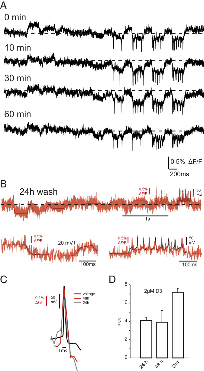
Long-lasting optical measurements of membrane voltage following removal of the acceptor/quencher D3 from the extracellular space. (A) Individual traces of raw unfiltered and unprocessed fluorescent signals (sampled at 1.08 kHz) of membrane potential changes following the indicated times after the washout of 10 μM D3 from the recording chamber. The current injection protocol is the same as that shown in Figs. 2 and 3. Each protocol required a 6-s continuous illumination and was repeated four times every 10 min. Despite the multiple exposures to light, the SNR (z-score) of the first AP in the train was remarkably constant over time (at 0 min: 13.8 and at 60 min: 12.2). (B) Simultaneous optical (red) and electrical (black) recording from a mouse cultured neuron recorded 24 h after 10 min of incubation in 2 µM D3. The patch-clamp recordings in the I-clamp configuration (black) were sampled at 50 kHz. (Upper) Whole trace of current pulses of 300-ms duration injected into the neuron to produce hyper- and depolarizations of the membrane and AP firing. (Lower) Enlarged snapshots of hyerpolarizing (Lower Left) and depolarizing (Lower Right) current injections. (C) Superimposed average trace of five AP waveforms induced in a HEK293T cell expressing GPI-eGFP measured 24 and 48 h after 10 min of incubation with 2 µM D3. (D) Bar graph showing SNRs 24 and 48 h after incubation compared to Ctrl. Error bars indicate ± SEM.
Comparison of DPA and D3 on Passive Membrane Properties and AP Firing.
One of the major concerns with the dqGEVI approach is that the small-molecule quencher accumulates in the membrane sufficiently to cause considerable changes in capacitance and impede AP firing. The exact concentration threshold for DPA to cause such changes has not been adequately investigated but reports exist that at 5 μM DPA has deleterious effects on evoked responses in hippocampal slices (21). However, no such effects have been reported after incubation of slices with 4 μM DPA when it was used in conjunction with a new membrane-targeting approach for fluorescent proteins (29). First, we established that there was no difference between the AP width at half-amplitude between the cells expressing GPI-eGFP (mean ± SEM: 1.63 ± 0.26 ms, n = 16) and those that did not express the fluorescent protein (1.32 ± 0.07 ms, n = 36; P = 0.4878, Mann–Whitney U test). Next, we compared the effects of DPA and D3 on passive membrane properties and AP firing of cultured neurons without the expression of eGFP. We started by measuring the effects of 20 μM D3 (in 0.2% DMSO), a concentration twofold higher than we normally used for optical measurements, on whole-cell capacitance, input resistance, AP width at half-amplitude, and AP threshold. None of these parameters was affected by 20 μM D3 (SI Appendix, Fig. S2). In another series of experiments we systematically compared the effects of 0.2% DMSO; 2.5, 3, or 5 μM DPA (dissolved in 0.025, 0.03, and 0.05% DMSO, respectively); and 10 or 20 μM D3 (dissolved in 0.1 and 0.2% DMSO, respectively) on the same membrane parameters. The starting values for each of the properties were not different between the cells. In contrast to D3 and DMSO, DPA significantly increased membrane capacitance and AP width at half-maximal amplitude (SI Appendix, Fig. S3 A and B). The values prior to perfusion were compared to those measured at 5 or 10 min after the perfusion of the compounds. The concentration of DPA used was commensurate with that customarily employed in hybrid voltage sensing (21, 24, 29). In addition to increasing the membrane capacitance, 3 μM DPA had a toxic effect on the cells, as gradually fewer and fewer neurons survived for the entire duration of the 10-min perfusion (SI Appendix, Fig. S3C). In a small number of cells (n = 3) that expressed GPI-eGPF and lasted sufficiently long in 3 μM DPA we wanted to compare the optical recordings to those we obtained with D3. Unfortunately, in none of the recorded neurons did we obtain any fluorescent signals that correspond to evoked APs. It is possible that D3 and DPA have different energy requirements for voltage-dependent movements or changes in orientation in the membrane and therefore do not have similar charging effects. In the case of D3 such energy requirements may be sufficiently low not to perturb the passive membrane properties.
Lack of D3 Effects on Synaptic Responses in Slices.
Another considerable concern with the use of the two-component voltage measurement approach with DPA is its effect on ligand-gated ion channels. DPA and other hydrophobic anions have been reported to antagonize GABAA (33, 34) and NMDA receptors (35). Therefore, we wanted to test the effects of 10 μM D3 on excitatory and inhibitory synaptic responses recorded in cortical slices. We recorded spontaneous excitatory postsynaptic currents (sEPSCs) (at Vh = −60 mV) and spontaneous inhibitory postsynaptic currents (sIPSCs) (at Vh = 0 mV) in L2/3 pyramidal cells of mouse cortical slices at 32 ± 1 °C. In eight neurons values are given as follows (mean ± SEM before D3 perfusion; at the end of a 10-min 10 μM D3 perfusion; the respective P values obtained by a Wilcoxon matched-pairs signed rank test): the frequencies of sEPSCs (6.55 ± 2.34 Hz; 5.90 ± 1.46 Hz; P = 0.8438) and sIPSCs (8.83 ± 1.91 Hz; 9.33 ± 1.61; P = 0.5469), 20 to 80% rise times of sEPSCs (1.29 ± 0.38 ms; 1.44 ± 0.43 ms; P = 0.4609) and sIPSCs (1.53 ± 0.38 ms; 1.32 ± 0.28 ms; P = 0.8438), weighted decay time constants for sEPSCs (6.93 ± 1.07 ms; 8.22 ± 1.12 ms; P = 0.1484) and sIPSCs (11.25 ± 0.65 ms; 10.64 ± 0.51 ms; P = 0.6406), and peak amplitudes of sEPSCs (13.47 ± 3.16 pA; 11.46 ± 2.09 pA; P = 0.3125) and sIPSCs (19.14 ± 1.07 pA; 20.96 ± 1.65 pA; P = 0.3828) were all unchanged by D3.
Discussion
We have discovered a FRET pair for a dqGEVI approach. Over the past decades, the dqGEVI method has been using the same small-molecule voltage sensor, DPA. The quenching compound D3 in combination with the membrane tagged GPI-eGFP performs better than previous FRET quenching pairs used for dqGEVI. In addition, at concentrations required for optical voltage sensing, D3 has a considerable advantage by not altering passive membrane properties or AP characteristics and by not affecting synaptic responses in cortical neurons. Moreover, it shows a linear response to voltages over a wide range (−100 to +40 mV) of membrane potentials, unlike the DPA-hVOS 1.5 or 2.0 probes that are less than optimal for recording membrane hyperpolarizations (29) and exhibit remarkably slow single-photon excitation photobleaching properties. Using no optical refinement or pixel enhancement methods, the D3-GPI-eGFP dqGEVI shows a satisfactory voltage sensitivity (6.6% ΔF/F per 100 mV) which is on average less than those of single-component GEVIs (6, 10). At our highest sampling rate of the fluorescence (∼2.2 kHz) D3-GPI-eGFP showed a remarkable speed and accuracy of detecting APs as well as subthreshold depolarizing and hyperpolarizing responses without the need for signal averaging and pixel enhancement techniques. In GEVI recordings we performed a ROC analysis of optical AP detection. The values obtained for the sensitivity, specificity, DOR, and AUC of AP detection at 50 Hz and 100 Hz are truly remarkable and provide the basis for the future use of the dqGEVI approach presented here for the detection of APs in fast spiking cells, such as interneurons. At the low light intensities used, there was little bleaching observed, and recordings with good SNR could be maintained for over 60 min. The observation that D3 does not need to be present in the extracellular environment is also promising as it will permit preloading the plasma membrane with the molecule prior to in vivo experiments. Since eGFP has a much longer photobleaching half-time compared to the cerulean-based (43) hVOS 1.5, our approach should also be suitable for longer exposures to excitation light. Based on our preliminary findings possible differences between the membrane movements and orientations between DPA and D3 should be further explored in order to advance the dqGEVI approach. A way to improve upon ΔF/F is to increase the Förster radius (R0), which can be described as (44) follows:
Compared to single-molecule GEVIs (6, 10) and other two-component GEVI approaches that do not use dark quenchers (16, 17, 45, 46) our approach may lack in the magnitude of ΔF/F response for a given voltage, but it makes up for this with a high SNR, lack of fast photobleaching, and a highly accurate and rapid electrical signal rendering without the need for averaging and pixel manipulations. The use of GEVIs in mice has been rendered considerably easier with the development of the Optopatch3 mouse line (13), but the use of GEVIs in other preparations such as neurons derived from human iPSCs (47) has not been widespread. Our dqGEVI approach works well in both dorsal root ganglion cells and cortical neurons derived from human iPSCs, presenting a stage where its many superior properties will be useful for unperturbed recordings of membrane potential changes.
Materials and Methods
Animals.
Timed-pregnant Wistar rats and C57BL/6N mice were used to prepare cell cultures between days 16 and 18 of embryonic development. Adult (>11 wk old) C57BL/6N mice of both sexes were used to prepare brain slices. All animal storage, handling, and experiments were conducted in accordance with the guidelines of the Animal Care and Use Committee of the University of Bonn.
Cell Cultures.
For cell culturing, molecular biological, and virus preparation procedures all reagents were purchased from Thermo Scientific unless indicated otherwise. Cortical neurons were obtained from Wistar rats or C57BL/6N mice mice between days 16 and 18 of embryonic development. Pregnant rats or mice were anesthetized with isoflurane and decapitated and the embryos were removed from the uterus. After decapitation of the embryos, the cortices were isolated in HBSS buffer and digested with trypsin (0.25%) and DNase I (1 mg/mL, purchased from Sigma). Cells were cultured in the mixture of basal medium Eagle enriched with fetal bovine serum (1%), B-27 supplement (2%), glucose (1%) and l-glutamine (0.23%). Cells were plated at a density of 20,000 to 35,000 cells per well onto poly-d-lysine–coated coverslips (d = 12 mm) in a 24-well plate. Twenty-four hours after preparation the plating medium was changed to 1 mL of fresh medium per well. As a second approach, we also used frozen cell stocks of rat cortical neurons (AMS Biotechnology). These were revived and put into culture according to the manufacturer’s instructions with a plating density of 35,000 cells per well. All culturing procedures were similar to those described for the primary mouse neuronal cultures above. HEK293T cells were purchased from ATCC (CRL-3216) and cultured in DMEM bathing medium (+10% fetal calf serum and 1% penicillin–streptomycin). Cells were grown under standard conditions (37 °C, 5% CO2) and transfected with Lipofectamine 3000 according to the manufacturer’s protocol.
Molecular Biology.
The pCAG:GPI-eGFP plasmid (48) encoding a fusion protein of proacrosin signal peptide, eGFP, and Thy-1 GPI anchoring signal (GPI-eGFP) was purchased from Addgene (Plasmid 32601; deposited by Anna-Katerina Hadjantonakis) as well as pAAV-hSyn-ASAP2s (Plasmid 101276; deposited by Francois St-Pierre). All other reagents were purchased from Thermo Scientific, if not indicated otherwise. To minimize nonneural expression, the open reading frame for GPI-eGFP was cloned to an AAV plasmid backbone (pAAV Syn1:MCS) under the human synapsin-1 promoter (49) with the XbaI and HindIII restriction sites (primers: forward XbaI GPI_KOZ and reverse HindIII GPI).
Virus Preparation and Transduction Procedures.
Recombinant adeno-associated virus production and preparation were carried out as previously described (50, 51). Briefly, plasmids for viral vector production were grown in DH5 alpha bacteria while HEK293T cells (ATCC CRL-3216TM) were transfected using the CaPO4 method. Virus particles were harvested 4 or 5 d after transfection and subsequently purified with HiTrap Heparin HP columns (GE Healthcare Life Sciences). After concentration and sterile filtration, viral proteins were separated using denaturizing polyacrylamide gel electrophoresis to detect major viral proteins VP1, VP2, and VP3 for quality control. For transduction of cultured neurons, virus particles were diluted in sterile phosphate-buffered saline and were added directly to the bathing medium.
Confocal Imaging.
To demonstrate plasma membrane targeting of the GPI-eGFP fusion protein, images of transgene-expressing neurons were taken at 40× magnification on a TCS SP5 confocal platform and on an Olympus IX81 confocal microscope (Olympus Corp.). Cells were fixed with 4% paraformaldehyde for ∼3 min and then coated with Vectashield mounting medium (Vector Laboratories).
Combined Optical and Electrophysiological Recordings.
Reagents for electrophysiological experiments were purchased from Sigma unless indicated otherwise. Most experiments were conducted using an Olympus BX61WI microscope (Olympus Corp.) equipped with epifluorescence and differential interference contrast. An EM-CCD camera (Evolve 512 Delta with LightSpeedTM) or a metal–oxide–semiconductor (CMOS) camera (Prime 95b, both cameras from Teledyne Photometrics) were used to visualize neurons and to verify fluorescence. Both cameras were controlled by μManager software (52). Expression of GPI-eGFP was verified using epifluorescence. Excitation illumination (470 nm) at 4.3 mW × mm−2 was provided with a custom-made light source (parts from Thorlabs Inc. with a Luxeon Rebel 470-nm light-emitting diode [LED] LXML-PB01-0040) that was driven by a custom-made transistor–transistor logic (TTL) switched stable current source. The excitation light as well as the collected fluorescence were filtered using a FITC filter set (Ex: HQ480/40×; Di: Q505LP; Em: HQ535/50m; Chroma Technology Corp.). For optical voltage imaging with the EM-CCD camera two different settings were used. Frame rates of ∼1.08 kHz were achieved by measuring a 100- × 100-pixel ROI without binning. In order to gain more precise timing of the optically recorded peak of electrical events we also applied 4- × 4-pixel binning in a 100- × 80-pixel ROI resulting in 25- × 20-pixel ROI and frame rates of ∼2.225 kHz.
For optical voltage imaging with the CMOS camera frame rates of 976 Hz were achieved by measuring a 96 × 96 pixel ROI. The timing of illumination and image acquisition were controlled by a digital stimulator (PG4000A; Cygnus Technology Inc.) that was triggered by the acquisition software WinWCP. No image processing was applied.
For dendritic recordings a Redshirt FastCMOS 128x camera mounted to a SliceScope Pro-1000 microscope (Scientifica) reconstructed using parts of the Olympus BX61WI by Scientifica was used. Excitation illumination (488 nm) at this setup was provided by an excelsior-488C-200_CDRH laser (Spectra-Physics) with a maximum power of 200 mW. During the dendritic measurements the laser power was set to 75 mW measured at the end of the light fiber. Frame rates of 10 kHz were achieved at full frame of 128 × 128 pixels (pixel size 15 µm) without binning. Recordings were started after a ∼45-min preincubation period with artificial cerebrospinal fluid (ACSF) containing of 4-AP (50 µM) and the D3 (Millipore Sigma) (2 to 10 μM) in 0.02% DMSO at room temperature. Whole-cell patch clamp recordings were amplified using a Multiclamp 700B amplifier (Molecular Devices), low-pass-filtered at 10 kHz and digitized at 50 kHz with an NI USB-6341 (National Instruments) controlled by Strathclyde Electrophysiology software WinWCP (John Dempster, University of Strathclyde, Glasgow, United Kingdom). Data were stored on a hard disk for offline analysis. Pipettes were pulled from borosilicate glass (King Precision Glass, Inc.) using a DMZ Zeitz puller (Zeitz-Instruments). Patch pipettes had resistances of 3 to 5 MΩ and contained (in millimolar): 135 K-gluconate, 5 KCl, 10 Hepes, 0.1 ethylene glycol-bis(2-aminoethylether)-N,N,N′,N′-tetraacetic acid (EGTA), 1 MgCl2, 3 MgATP, and 0.2 Na2ATP at pH 7.2. GPI-eGFP–expressing cultured neurons 2 to 3 wk after viral transduction were transferred to a modified submerged chamber (52) and perfused with Hepes-buffered ACSF (3 mL/min at 32 ± 1 °C, in millimolar): 145 NaCl, 5 KCl, 1.5 CaCl2, 2 MgCl2, 26 2-(4-(2-hydroxyethyl)-1-piperazinyl)-ethanesulfonic acid (Hepes), and 10 glucose at pH 7.4. Recordings were started after a ∼5 min preincubation period with ACSF containing D3 (10 μM) in 0.1% DMSO.
Imaging sequences were analyzed using ImageJ (53) and Igor Pro (Wavemetrics Inc.). Average gray values were extracted from the image sequences using the Z profiler-plugin for ImageJ. The precise timing of the images was obtained by digitally recording the “exposure out” TTL signal given off by the camera. This signal was then imported into Igor Pro and the rising and falling edges of the TTL pulses were detected. The midpoints between the detected edges constituted the precise time points for the image acquisition, which were then lined up with the digitized electrophysiology traces. The optically recorded AP peak and the decay time constant of the AP were analyzed in recordings with 2.225-kHz sampling. Exponential fits of the electrophysiological and optical signals were made using IgorPro. The SNR (z-score equivalent) for APs was measured as the ΔF/F of the AP divided by the SD of the 200-ms prior baseline (29) that contained no obvious spontaneous activity in the electrical recording. To analyze the ability of the dqGEVI approach to faithfully report high-frequency AP firing, trains of 16 or 21 high-amplitude (800 to 1,500 pA) 4-ms current pulses were applied at a frequency of 50 or 100 Hz in the I-clamp configuration. Prior to AP detection, fluorescent traces were detrended, smoothed using the Savitzky–Golay method by a 17-point (for 2.225-kHz sampling) and 7-point (for 1.08-kHz sampling) fourth-order polynomial, and aligned with the electrophysiological traces as described above. Detection threshold for optical APs was set as 75% peak amplitude of the first fluorescent AP in the train relative to the mean 180-ms prior baseline period. AP threshold in the electrophysiological (Vm) trace was set at 0 mV. In some of the cultured neurons APs and failures were not clearly distinguishable in the electrophysiological recording. Therefore, traces with events that exceeded −20 mV but did not reach 0 mV were omitted from analysis. To elicit spontaneous activity in a synaptically connected network of cultured neurons and to record from multiple neurons simultaneously, the K+-channel antagonist 4-AP was added to the ACSF. In some of the experiments simultaneous electrophysiological recordings from one of the imaged neuron was also performed.
Chirp Function and Phase Determination.
The 10- to 100-Hz chirp function was generated by the following equation: A × sin[2π(F0 + ((Fmax − F0) × t/2T) × t)], where A is 50% of the peak-to-peak amplitude, F0 is the starting frequency (10 Hz), Fmax is the frequency at the end of the pulse (100 Hz), t is time, and T is the duration of the chirp pulse (4 s). This pulse, generated at a sampling rate of 1,000 s−1, was fed into the digital-to-analog converter and subsequently low-pass-filtered at 300 Hz before feeding it into the amplifier to circumvent step-like changes in Vm. For determination of the phases of the equivalently sampled and mean subtracted ΔF/F and Vm signals, we first used the HilbertTransform function built into IgorPro. The phase was then determined by the value of the atan function of the point-by-point division between the HilbertTransform/signal.
Assessment of Quencher Effects on Passive and AP Properties.
Nonfluorescent cultured neurons aged similarly to those used for combined optical and elecrophysiological recordings were used for these experiments. The procedures for whole-cell I-clamp recordings were identical to those described for the electrophysiological recordings above. Data were analyzed using Igor Pro. For passive membrane properties, a 300-ms hyperpolarizing voltage pulse was elicited by current injection every 5 s for a 5-min baseline period followed by the bath perfusion of the vehicle (0.2% DMSO) or the quencher, that is, 3 μM DPA (Biotium) (in 0.03% DMSO) or 10 or 20 μM D3 (in 0.1 and 0.2% DMSO, respectively) for 10 min. Membrane time constants were assessed by fitting an exponential to the hyperpolarization. APs were elicited by 200-ms-long depolarizing current injections. AP threshold was determined from the first peak of the third derivative of the voltage signal (54). AP full width at half amplitude was determined as the time difference between the two points between the rising and decaying phases of the APs both at 50% of AP amplitude.
Slice Recordings.
Wild-type C57BL/6N mice (aged 11 to 14 wk) were anesthetized with isoflurane and decapitated. Brains were quickly removed and transferred into ice-cold cutting solution containing (in millimolar) 60 NaCl, 100 sucrose, 2.5 KCl, 1.25 NaH2PO4, 26 NaHCO3, 1 CaCl2, 5 MgCl2, and 20 glucose (pH 7.3). Three hundred-micrometer coronal slices were prepared with a vibratome (Leica VT1200S) and gradually warmed to 37 °C. For electrophysiology, slices were transferred into a submerged chamber (55) and superfused with ACSF containing (in millimolar) 125 NaCl, 3.5 KCl, 1.25 NaH2PO4, 26 NaHCO3, 2 CaCl2, 2 MgCl2, and 15 d-glucose (pH 7.3) and allowed to equilibrate for at least 20 min at room temperature. All solutions were bubbled with 95% O2–5% CO2. Whole-cell voltage clamp recordings were performed on visually identified cortical layer 2/3 pyramidal neurons. Patch pipettes (3 to 6 MΩ) were filled with (in millimolar) 135 Cs methansulfonate, 5 KCl, 10 Hepes, 0.16 EGTA, 2 MgCl2, 3 NaCl, 4 Na2-phosphocreatine, 2 MgATP, and 0.2 NaGTP (pH adjusted to 7.3 with CsOH, osmolarity 290 mosm/kg). Signals were low-pass-filtered at 3 kHz and sampled at 10 kHz. Series resistance was monitored before and after the recording. Experiments with series resistances >20 MΩ or a change >20% during the recording were excluded. sEPSCs were recorded at a holding potential (Vh) of −60 mV. sIPSCs were recorded at a Vh of 0 mV. sEPSCs and sIPSCs were recorded starting during a 2- to 3-min baseline period before bath application of 10 μM D3 in 0.1% DMSO and then continuously during D3 perfusion for >10 min. Events were analyzed during 1-min epochs collected during the baseline period and at least 10 min after bath application of D3. Data were analyzed using a custom-written LabView software (EVAN) which provided peak amplitudes, 20 to 80% rise times, weighted decay time constants, and averaged traces.
Quantification and Statistical Analyses.
Cohen’s d (difference between two means M1 and M2) was calculated as d = ABS(M1 − M2)/SD, where SD is the pooled SD given by SD = SQRT((SD1^2 + SD2^2)/(N1 + N2 − 2)). Here SD1 and SD2 are the sample SDs of the two distributions, respectively, and N1 and N2 are the two corresponding Ns. The cross-correlation coefficients between the ΔF/F and Vm were normalized by dividing the value by RMS(ΔF/F) × SQRT[N(ΔF/F)] × RMS(Vm) × SQRT[N(Vm)]. Statistical significance levels were set at P < 0.05. For analysis of the fidelity of high-frequency AP firing, we performed a ROC analysis. The DOR was calculated (41) as (a/b)/(c/d), with a = true positives, b = false negatives, c = false positives, and d = true negatives, with the respective values indicated in Fig. 6. The AUC was calculated as
with dx = 0.01. All formulas for calculating the parameters of the ROC analysis are given in Fig. 6.
All results are expressed as mean ± SEM unless otherwise stated. Using variance estimates from the literature or from our own preliminary data, a power analysis was done to estimate the required sample size to obtain a power of 0.80, for a moderate effect size (0.25), and a significance level of 0.05. Statistical tests used for data comparisons and significance calculations are indicated for each comparison. Significance level was set at P < 0.05.
Acknowledgements
This research was initially supported by European Research Council Advanced Grant 339620 MULTIGEVOS. We thank Phuong Tran and Lydia Fischer for excellent technical assistance, S. Schoch and her laboratory for help with virus preparation, H. Beck for his generous help providing the Prime95B camera and him and his laboratoy members for discussions and comments, S. Remy and his laboratory members, F. Fuhrmann and H. Kaneko for their generous help and for the use of the setup for the dendritic recordings, W. F. Kunz for the use of the spectrophotometer, A. Zimmer’s group for use of indispensable equipment, S. Opitz for preparation of cultured neurons, and M. Schwarz for confocal imaging. We acknowledge the assistance of the Microscopy Core Facility of the Medical Faculty within the Bonn Technology Campus Life Sciences, University of Bonn.
Data Availability.
Excel files, Igor files, and Image files have been deposited in Sciebo (https://uni-bonn.sciebo.de/s/bd1mYM2AKbQXt7i). All study data are included in the article and/or SI Appendix.
References
1
2
3
4
6
7
8
9
10
11
12
13
14
15
16
17
18
19
20
21
22
23
24
25
26
27
28
29
30
31
32
33
34
35
36
37
38
39
40
41
42
43
44
45
46
47
48
49
50
51
52
53
54