
Certain bird species have evolved spectacular colors that arise from organized nanostructures of melanin. Its high refractive index (∼1.8) and broadband absorptive properties enable vivid structural colors that are nonsusceptible to photobleaching. Mimicking natural melanin structural coloration could enable several important applications, in particular, for noniridescent systems with colors that are independent of incidence angle. Here, we address this by forming melanin photonic crystal microdomes by inkjet printing. Owing to their curved nature, the microdomes exhibit noniridescent vivid structural coloration, tunable throughout the visible range via the size of the nanoparticles. Large-area arrays (>1 cm2) of high-quality photonic microdomes could be printed on both rigid and flexible substrates. Combined with scalable fabrication and the nontoxicity of melanin, the presented photonic microdomes with noniridescent structural coloration may find use in a variety of applications, including sensing, displays, and anticounterfeit holograms.
Nature provides a myriad examples of living organisms that have evolved intricate ordered nanostructures that produce beautiful colors via light interference instead of material absorption.1,2 Such natural structural coloration (SC) has inspired the development of engineered nanophotonic materials, which circumvent limitations of traditional coloration strategies based on pigments or dyes.3,4 Not least, organic dyes tend to fade over time, and inorganic pigments are often based on toxic heavy metals, with harmful effects on the environment and human beings.5
Although there are many top-down fabrication methods to prepare artificial SC devices, bottom-up approaches are preferred for most practical applications due to scalability and low cost.6−11 In particular, SC systems have been commonly prepared by convective self-assembly of spherical polymeric or silica nanoparticles (NPs) into three-dimensional planar thin film photonic crystals.12,13 These colloidal crystals produce iridescent colors, which means that they reflect different colors at different angles. This limits their suitability for many applications, such as color displays with wide viewing angles or photonic paints. Previous approaches to reduce the angular dependence of SC include fabrication of nonplanar systems and short-range-ordered amorphous assemblies of NPs.14,15 However, color saturation is often limited due to incoherent light scattering that contributes to a broad background signal.16 To suppress such white background and improve color hue, researchers have incorporated light-absorbing materials such as carbon black into colloidal NP assemblies.17−19 An alternative approach, which avoids the need for black additives and thereby facilitates better control of the self-assembly process, uses NPs made of partially light-absorbing materials, such as melanin. In this way, the NPs themselves contribute to suppressing incoherent scattering.20−22 Interestingly, similar systems can be found in Nature via Avian birds that produce SC using melanin NPs (MNPs).23,24
From an application point of view, it is desirable to enable well-controlled and precise patterns of noniridescent SC, for which inkjet printing of NP-containing droplets that self-assemble into microdomes is a promising approach.15 Inkjet printing provides precise and reproducible deposition of small microdroplets with diameters down to only a few micrometers.25 The technique also offers flexibility in creating high spatial resolution patterns over large areas at low cost and low material usage, which open avenues for wide-ranging applications in sensing, encryption, and displays.26,27 On the other hand, printing of NP inks that form suitable microdroplets that also self-assemble into microdomes with high NP order is challenging as it requires several different aspects to be jointly fine-tuned. To our knowledge, this was not yet achieved for melanin-based systems.
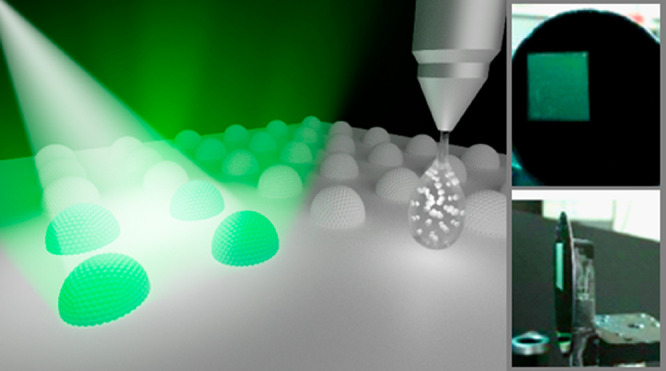
In this work, we demonstrate inkjet printing of photonic MNP microdomes with high order (schematically depicted in Figure 1a). The microdomes provide highly vivid SC that is noniridescent. We synthesized MNPs of different sizes (around 100–300 nm) and formulated printable inks using a high boiling point binary cosolvent, allowing stable jetting with high printing efficiency and spatial uniformity. Solvent evaporation resulted in confined self-assembly of MNPs into microdomes with high order and bright SC, as exemplified in Figure 1b,c, respectively. Varying MNP size enabled printing of red, green, and blue (RGB) photonic microdome pixels, as studied in detail by microreflectance spectroscopy, optical microscopy, and electron microscopy. We demonstrate inkjet printing of large-area arrays (>1 cm2) of photonic MNP microdomes and show that they provide bright and highly noniridescent SC, not only for specular reflection but also for diffusive and back-scattered light. Printing was successful on various substrates, including on flexible polydimethylsiloxane (PDMS) and rigid silicon wafers.

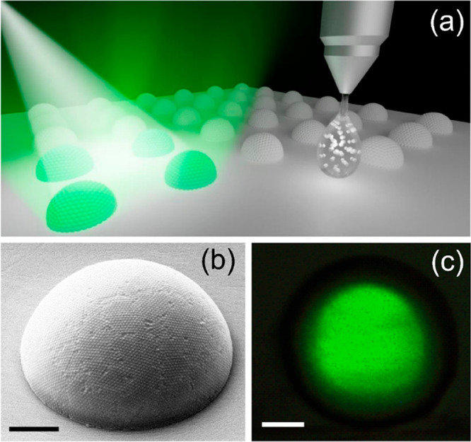
(a) Schematic illustration of inkjet-printed MNP photonic microdomes. (b) Scanning electron microscopy image of a typical inkjet-printed MNP photonic microdome (tilted at 54°). (c) Optical microscopy bright-field image showing green SC from a typical inkjet-printed MNP microdome. The scale bars in (b) and (c) are 3 μm.
We prepared MNPs by polymerizing dopamine hydrochloride monomers in a water–methanol solution, as illustrated in Figure S1 and explained in detail in the experimental section of the Supporting Information (SI). We could accurately tune the size of the MNPs by changing the monomer concentration, enabling MNPs from approximately 110 to 260 nm (red squares in Figure 2a). The scanning electron microscopy (SEM) image in the inset of Figure 2a confirms that the MNPs are spherical and uniform in size. Indeed, the size distribution in terms of coefficient of variation (CV) is below 10% for all particle sizes (blue circles in Figure 2a). Such low polydispersity is key to create SC by self-assembly into photonic crystals.28 The MNPs showed a clear negative zeta-potential (average −38 ± 2 mV), which results in electrostatic repulsion between MNPs and thereby led to stable MNP dispersions.
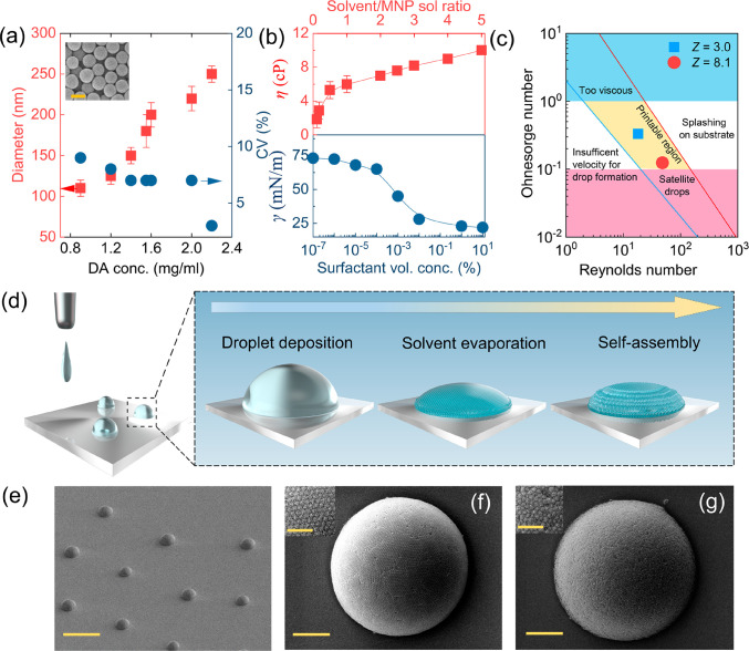
(a) Diameter and CV of MNPs as a function of monomer concentration. The inset shows an example of a SEM image of MNPs, as used to measure nanoparticle sizes (scale bar = 200 nm). (b) Viscosity (top panel) and surface tension (bottom panel) of MNP inks as a function of solvent content and surfactant concentration, respectively. The top panel x axis represents the ratio of solvent to MNP aqueous solution, using single solvent for ratios between 0 and 1 and binary solvents for larger ratios. (c) Phase diagram showing different operating regimes in inkjet printing. Inks with conditions optimized for both printing and ordered self-assembly are indicated with the blue square, whereas the red circle corresponds to printable ink, but less ordered MNP self-assembly. (d) Schematic visualization of inkjet printing and self-assembly of photonic MNP microdomes. (e) SEM image of several printed photonic MNP microdomes. The scale bar is 30 μm. (f) Representative high-magnification SEM micrographs of a photonic MNP microdome made using an optimized ink containing MNPs with diameter of 204 nm. (g) Same as in (f), but using the non-optimized ink. The scale bars are 3 μm. The insets in (f,g) are magnified SEM images, with scale bars of 1 μm.
To be compatible with inkjet printing, the inks need suitable rheological properties, which are related to the Reynolds (Re) and Ohnesorge (Oh) numbers:29


In order to determine suitable concentrations for ink formulation, we construct a phase diagram with Re and Oh on the x and y axes, respectively (Figure 2c).29 The shaded yellow region in the middle of the diagram corresponds to properties that are suitable for inkjet printing. Regions toward the edges of the diagram are not suitable due to, for example, the likelihood of splashing on the substrate, formation of satellite drops, or clogging of the nozzle due to higher ink viscosity. Printability of inks can also be estimated via the reciprocal of the Ohnesorge number (Z = 1/Oh), with best printability in the range 10 > Z > 1.30 Too low Z prevents printing due to too high pressure from the high viscosity, whereas too high Z results in generation of satellite droplets. Based on fixed nozzle diameter of 21 μm and droplet velocity of 7 m/s (suitable values lie in the range from 6 to 10 m/s),30 we formulated printable inks by adjusting Re and Oh (and Z) via the FAEG and surfactant concentrations. This enabled formulation of inks with properties in the center of the printing region of the phase diagram (blue square; η = 7 cP, γ = 28 ± 2 mN/m, Z = 3.0). We also prepared less optimized inks with the single formamide solvent (red circle; η = 3 cP, γ = 28 mN/m, Z = 8.1), for which printing was possible but resulted in satellite droplets (see Figure S2). We also note that droplet formation upon jetting is influenced by the applied waveform over the ink, which affects droplet ejection and shape.34 This is particularly relevant for our inks that contain NPs. Figure S3 shows customized waveform profiles for stable droplet ejection for the MNP inks.
Figure 2d shows a schematic illustration of the MNP self-assembly process into microdomes after deposition on the substrate. After printing, solvent evaporation leads to shrinking of the microdroplet while maintaining its dome shape. In this process, the dispersed MNPs come closer together, and when the MNP concentration reaches a critical value, they begin to crystallize, resulting in assembly of hemispherical microdomes.35Figure 2e shows a SEM image of successful printing and assembly of MNP microdomes on a hydrophobic PDMS substrate (we used hydrophobic substrates to ensure high contact angles). These microdomes originate from printing of 10 pL droplets of an optimized ink (Z = 3.0) containing 5 wt % 204 nm in diameter MNPs, resulting in around 15 μm hemispherical colloidal assemblies with high contact angle (∼60°). Closer inspection of a single microdome shows highly uniform, well-packed, and long-range-ordered MNPs, with crystalline patches resembling those of a soccer ball. Each large patch/domain shows hexagonally packed MNPs (Figure 2f).36,37 Grain boundaries and point defects on the surface of the microdomes can be attributed to stress and strain developed during the crystallization process, as discussed previously by Ling and co-workers for spherical assemblies of polystyrene microparticles.38 The average domain size was typically between 3 and 6 μm. To reveal the internal structure of the MNP microdomes, we cut them open with a focused ion beam (FIB) and imaged their interior by SEM (see Figure S4). All examined MNP microdomes consisted of MNP layers from top to bottom, without any hollow regions. Such a highly ordered multilayer MNP structure makes the microdomes promising for SC.
It should be noted that ink printability is not sufficient to obtain microdomes with high MNP order. We demonstrate this by printing microdomes with inks with lower viscosity and higher Ohnesorge number (Z = 8.1), made using a single formamide solvent instead of the binary FAEG solvent. This non-optimized ink produced microdomes with a size similar to that for the optimized ink, but with non-closed-packed MNPs resembling colloidal photonic glass (Figure 2g).39 We attribute the lower order to the lower viscosity (∼3 cP) and higher evaporation rate of this ink compared with the optimized ink, highlighting the importance of finding the suitable relation between MNP movements and microdroplet evaporation during the crystallization process.
Optical microscopy and microreflectance spectroscopy enabled us to reveal how MNP size and packing order influence the optical properties of the microdomes. Figure 3a shows optical microscopy images of microdome arrays printed on PDMS using optimized inks (Z = 3.0) containing MNPs of different sizes. The microdomes are uniform in size and shape and could be precisely positioned over large areas. The slight nonperfect alignment of the microdomes within the array could be related to the printing itself (e.g., varying jetting angle) or to contraction and movement of the droplets and particles during the self-assembly process. The microdomes all show strong reflective SC, with highly vivid colors and excellent uniformity between pixels. The different colors originate from MNPs of different diameters, enabling reproducible printing of red (i, 240 nm), green (ii, 204 nm), and blue (iii, 182 nm) photonic MNP microdomes. Because every printed droplet results in an individual reflective photonic micropixel, the results are promising for printing images or for pixelated reflective displays.
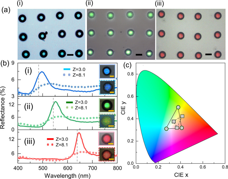
Optical properties of inkjet-printed photonic MNP microdomes. (a) Optical microscopy images of microdomes producing blue (i), green (ii), and red (iii) reflected SC, based on particles with diameter of 182, 204, and 240 nm, respectively. The scale bars are 20 μm. (b) Reflection spectra and micrographs of single photonic MNP microdomes, made from optimized inks (Z = 3.0, solid lines, top insets) and non-optimized inks (Z = 8.1, dotted lines, bottom insets), with SC tunable across the visible spectrum. Particle diameters are the same as in (a). The scale bars are 10 μm. (c) CIE chromaticity chart for reflected SC from single photonic MNP microdomes. The circles connected with solid lines correspond to the optimized photonic MNP microdomes, and the squares connected with dotted lines represent non-optimized photonic MNP microdomes.
The solid lines in Figure 3b show reflection spectra of individual photonic microdomes made from optimized inks with MNP sizes of 182 nm (i, blue), 204 nm (ii, green), and 240 nm (iii, red). The top insets in each panel are optical images of the same pixels. They all show sharp reflection peaks (full width at half-maximum ≈ 50 nm), resulting from Bragg diffraction by the highly ordered MNPs. The peak positions (λmax) can be estimated from the Bragg–Snell law:40
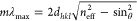
Figure 3b also presents the reflection spectra (dotted lines) and optical microscopy images (bottom insets in each panel) for single microdomes printed using the nonoptimized inks (Z = 8.1) but with same MNP diameters. Whereas these microdomes provide some SC, the colors are less pronounced and the reflection peaks are significantly broader and slightly red-shifted compared to those with the photonic MNP domes printed using optimized inks. The SC for these microdomes also shows significant spatial variation across the single pixels. We attribute these effects to the nonuniform and amorphous nature of the MNP packing for these microdomes, which leads to less efficient Bragg diffraction and a red shift due to larger average interparticle separation.
To provide a more intuitive appreciation of the color hues of the photonic microdomes, we converted the measured reflectance spectra to data points in the Commission Internationale de L’Eclairage (CIE) chromaticity chart (Figure 3c). As expected, the optimized photonic microdomes (round markers, connected via the solid black lines) display colors with relatively high chromaticity that are tunable by MNP size. By contrast, the limited MNP order of the non-optimized microdomes seriously affected chromaticity and resulted in muted and pastel-like colors (square markers, connected by the dashed black lines).
Re-examining the optical microscope images of the optimized photonic MNP microdomes reveals uniform color in the center surrounded by a dark rim. This phenomenon is related to the microdome shape and that the angle of the photonic crystal lattice varies gradually across the microdomes. In the center, the crystal lattice is parallel to the substrate, such that light at normal incidence will predominantly result in SC reflected back normal to the substrate. However, toward the rim of the domes, light incident normal to the substrate will experience a large incidence angle with respect to the photonic crystal lattice (up to around 60° at the edges). Therefore, the dominant part of the diffracted light will not reflect back from where it came. To verify this explanation, we imaged the same microdomes using microscope objectives of different numerical apertures (NA). Lenses with higher NA collect light from larger angles and should therefore collect back-reflected SC from a wider range of angles than lenses with low NA.41 Indeed, we found that the size of the colored center area of the microdome increased with increasing collection angle (measured from 9 to 53°; see Figure S5). The fact that the increase was also gradual is consistent with gradual tilting of the crystal lattice across the domes, which is promising for achieving noniridescent SC.
Next, we demonstrate that the photonic MNP microdomes provide highly noniridescent SC and that they can be used to form large area surfaces with angle-independent reflected colors. We inkjet printed a 1 × 1 cm2 square array of green photonic MNP microdomes (optimized ink with 204 nm MNPs, dome spacing of 40 μm) on a black substrate (Si wafer coated with thin layer of PDMS mixed with carbon nanotubes; see SI for details). In brief, the photonic microdome arrays provided vivid and highly noniridescent green SC for both specular reflection as well as for diffuse scattering and back scattering (see Figure 4). Figure 4a shows photographs taken for specular reflection at different angles, and the color remains essentially the same up to the largest incidence angle of 80°. Indeed, optical spectroscopy shows hardly any variation in the reflection peak position for different angles (blue triangles in Figure 4d, full spectra in Figure S6). By contrast, flat photonic crystal control samples made from the same MNPs (see SI for details) show significant angle dependence, following the Bragg–Snell law as expected (green circles and green full line in Figure 4d, respectively). As a result, flat photonic crystals completely change their appearance when viewed at different angles (see photographs in Figure S6c).
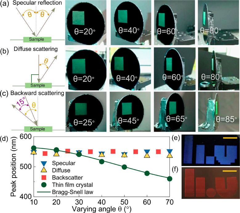
Noniridescence of inkjet printed photonic MNP microdome array made from 204 nm in diameter MNPs, printed on a Si substrate coated with a thin black PDMS layer (see SI). (a) Specular reflection: schematic of the measurement setup is shown to the left, followed by photographs at different incidence/detection angles. (b) Diffuse scattering: schematic of the measurement is shown to the left, followed by photographs at different detection angles. (c) Backward scattering: schematic of the measurement is shown to the left (only sample rotates), followed by photographs at different backscattering angles. (d) Reflection peak positions for the photonic microdome array at different angles obtained for specular (blue triangles), diffusive scattering (yellow triangles), and backward scattering (red squares). The green circles correspond to the flat photonic crystal control sample, and the green solid line corresponds to the predicted angle dependence from Bragg–Snell law. (e,f) Digital photographs of large-area blue and red prints inspired by our university logo (published with permission), printed on Si with black PDMS (e) and on black paper (f) and captured normal to the surface under ambient light conditions. The scale bars in (e,f) correspond to 1 cm.
Many practical applications, such as reflective displays, rely on nonspecular scattering for a good user experience. We therefore investigated the diffuse scattering properties for our photonic MNP microdome array by varying the detection angle while maintaining the incident light normal to the substrate. From the corresponding photographs (Figure 4b) and spectral response (yellow triangles in Figure 4d, full spectra in Figure S6), we conclude that the diffusive scattering from the photonic domes is highly noniridescent. We observe clear green scattering all the way up to an 80° detection angle. Similarly, the microdomes provide green back-scattered light (Figure 4c, by rotating the sample and keeping a fixed 15° angle between the light source and the detector), with minimal change in color for different angles (also see red squares in Figure 4d). The flat photonic crystal film provided only marginal diffusive and back scattering, highlighting the role of the microdome-shaped photonic crystals to obtain both noniridescence and nonspecular reflection. The results are consistent with results obtained for spherical NP assemblies (supraballs)22 and microdomes made of polystyrene NPs.15 Although originating from single photonic MNP microdomes, the noniridescence of our surfaces translates to the macroscale properties of the arrays. To further highlight the possibility for reproducible printing of photonic MNP microdomes in well-defined patterns over large areas, we printed a 3 × 1.8 cm image of our university logo using blue microdomes on black PDMS on Si (Figure 4e). We could also print large patterns with with vibrant SC on a black paper sheet (treated with octadecyltrichlorosilane to make it hydrophobic), although further work needs to investigate the exact shape and order of the MNP assemblies formed on the paper (Figure 4f). It was also possible to print images containing all three primary colors (see Figure S7), which could be further improved using printers with multiple cartridges to avoid need to change cartridges between colors.
In conclusion, we have demonstrated inkjet printing of MNPs and showed that they can assemble into microdomes that provide highly noniridescent SC with high chromaticity. This strategy supersedes conventional time-consuming self-assembly processes. MNP inks containing different NP sizes could be prepared and printed in accurate patterns on different substrates. Viscosity and surface tension of the inks played vital roles to both facilitate the printing and to obtain microdomes with high MNP order. Spectroscopic investigation of single photonic MNP microdomes showed that they behave as individual photonic crystals with spatially varying crystal orientation. Their structural color arise from Bragg diffraction, with colors tunable via MNP size. Our work highlights the advantages of fabricating biomimicking photonic pixels by inkjet printing, which can reduce processing times and material requirement compared with conventional self-assembly methods and provide the ability to create arbitrary patterns of noniridescent structural colors on a variety of substrates.
The Supporting Information is available free of charge at https://pubs.acs.org/doi/10.1021/acs.nanolett.0c02604.
Materials and methods, including synthesis and characterization of MNPs, MNP ink formulation, preparation of thin film photonic crystals, and structural and optical characterization; supplementary figures show SEM image of a satellite droplet, jetting waveform, FIB cut of a photonic crystal microdome, optical images of single microdomes imaged at different collection angles, optical images of color prints containing microdomes of different colors, optical spectroscopy of microdomes, and thin film photonic crystals (PDF)
R.S. and M.J. conceived the original idea. R.S. carried out the material synthesis, characterization, inkjet printing, optical characterization, and interpreted the data. S.S. assisted in setting up the microspectroscopy setup and initial inkjet printing. S.C. performed FIB-SEM measurement. S.G. contributed to angle-dependent spectroscopic measurements, and S.R. contributed to calculations and theoretical understanding. All work was coordinated by M.J. R.S. and M.J. wrote the manuscript through contributions of all authors. All authors has approved the final version of the manuscript.
The authors declare no competing financial interest.
We acknowledge financial support from the Wenner-Gren Foundation; the Swedish Research Council; the Knut and Alice Wallenberg foundation, the Swedish Foundation for Strategic research; the Knut and Alice Wallenberg foundation, Linköping University, and industry through the Wallenberg Wood Science Center the Wallenberg Wood Science Centre; and the Swedish Government Strategic Research Area in Materials Science on Functional Materials at Linköping University (Faculty Grant SFO-Mat-LiU No. 2009 00971). The authors thank Evan Kang for preliminary SEM data, and Subimal Majee for help with Ceradrop inkjet printing at Printed Electronics Arena (PEA), Norrköping.
 Noniridescent Biomimetic Photonic Microdomes by Inkjet
Printing
Noniridescent Biomimetic Photonic Microdomes by Inkjet
Printing
 Facebook
 Twitter
 Linkedin
 Whatsapp
