
Competing Interests: The authors have declared that no competing interests exist.
A compact fabric antenna structure integrated with electromagnetic bandgap structures (EBGs) covering the desired frequency spectrum between 2.36 GHz and 2.40 GHz for Medical Body-Area Networks (MBANs), is introduced. The needs of flexible system applications, the antenna is preferably low-profile, compact, directive, and robust to the human body's loading effect have to be satisfied. The EBGs are attractive solutions for such requirements and provide efficient performance. In contrast to earlier documented EBG backed antenna designs, the proposed EBG behaved as shielding from the antenna to the human body, reduced the size, and acted as a radiator. The EBGs reduce the frequency detuning due to the human body and decrease the back radiation, improving the antenna efficiency. The proposed antenna system has an overall dimension of 46×46×2.4 mm3. The computed and experimental results achieved a gain of 7.2 dBi, a Front to Back Ratio (FBR) of 12.2 dB, and an efficiency of 74.8%, respectively. The Specific Absorption Rate (SAR) demonstrates a reduction of more than 95% compared to the antenna without EBGs. Moreover, the antenna performance robustness to human body loading and bending is also studied experimentally. Hence, the integrated antenna-EBG is a suitable candidate for many wearable applications, including healthcare devices and related applications.
Over the past decade, the rapid development in communication systems for body sensor networks (BSN) has grown notably, supporting several applications ranging from patient monitoring systems, tracking, and emergency rescue systems to personalized health care systems and battlefield survival [1–4]. Many wireless standards were proposed for commercialization and research to support these growing developments, including the Medical Implant Communication Systems, Industrial, Scientific, and Medical (ISM). More recently, the Federal Communication Commission (FCC) introduced the MBANs frequency band covering the 2.36 GHz to 2.4 GHz spectrum due to its clean spectrum and low interference sources [5].
Improvements in efficiency and effectiveness of flexible/wearable antennas have become essential in light of these advances in Wireless Body Area Network (WBAN) application. An additional essential requirement for flexible/wearable antennas than traditional designs is to reduce the interaction between the radiating elements and the body tissue, despite being close to each other. It is noted that prolonged exposure to human tissue is controversial because it may exhibit health hazard effects [6]. To address this issue, consideration should be given to study the effects of flexible antennas on human tissue, such as the maximum allowable Specific Absorption Rate (SAR) [7–11]. Furthermore, to introduce lightweight, conformal, and low profile features [12, 13] into the antenna design criteria have further posed considerable challenges to meet the design's specification. The EBGs are proposed to divert the wearable antenna radiation from the human tissues. However, the previously reported structures with the integrated antenna in the area of wearable design have several disadvantages such as (i) the design could be too thick or electrically large to be suitable for the wearable systems [14–24], (ii) the design may be printed on semi-flexible materials which cannot withstand several bends [5, 12, 25–27] and (iii) the design may reveal poor Front-to-Back ratio (FBR) [28–31].
In this paper, a fully textile antenna with novel EBG for WBAN applications at 2.4 GHz is proposed. This work lays on the bandgap feature (Dispersion Diagram Technique) of EBG that cannot be demonstrated by earlier reported wearable EBG structures [8, 11, 12, 14–16, 18, 19, 22, 23, 25]. The bandgap feature is controlled by vias, such as in the case of mushroom-like EBG. It also may be achieved by a complex structure that can increase the effective inductance, such as multi-layered EBG, meander line EBG, fractal EBG, and interdigitated EBG. However, if the vias or complex structure is used, the risk of manufacturing inaccuracies is greater since the used material is fabric. Thus, designing EBG from fabric materials with a bandgap feature is challenging. Therefore, a simple and novel structure based on fabric materials that increased the effective inductance which introduces the bandgap feature is presented. The size is also reduced compared to several reported fabric EBG at 2.4 GHz [14–31].
In contrast to earlier documented EBG backed antenna designs, the proposed EBG behaved not only as a ground plane for shielding the antenna from the body but also as a radiator and reduced the reference antenna size. The proposed design contributes to enhancing the FBR, increasing the gain, and reducing the antenna's SAR level significantly.
It is worth to mention that compared with the lately recorded wearable antennas functioning in the super wideband [32], UWB [33], and UHF frequency bands [34], this article mainly emphasizes the realization of low profile, lightweight, flexible, and narrow-band wearable antenna for off-body communication in WBANs.
The paper is organized as follows. The physical structures of the EBG are presented, and the features are explained in Section 2. The experimental investigations and analysis of the integrated antenna with the EBG are discussed in Section 3. Section 4 presents the proposed antenna's performance in terms of the SAR value and the bending effect. Finally, conclusions are drawn in Section 5.
The fabric material with a permittivity of 1.7 and a thickness of 0.7 mm is used as a substrate. Simultaneously, a ShieldItTM material with a thickness of 0.17 mm is used for the conducting elements.
The antenna is designed based on the combination of F-shaped and U-shaped connected by a stripline. These shapes are formed by introducing specific slots and connected by stripline. The selection of the line widths, the slot lengths, and their positions are based on parametric studies. The design's evolution process is depicted in Fig 1, and their S11 is presented in Fig 2. In all design processes, the ground plane is fixed with Lg = 17.4 mm. The dimension of line widths and the slot lengths is presented in Table 1. Fig 2 shows the impact of introducing slots on the design. It can be seen that as the slots were introduced, the resonant frequency shifted to the lower band. The slots meandered, exciting the patch's surface current and lowered the antenna's resonance frequency to the desired frequency. The overall dimension of the finalized proposed design is 50×30×0.7 mm3.


Configuration of the reference antenna design (a) 1st design, (b) 2nd design, (c) 3rd design, (d) 4th design (reference antenna), and (e) Back view for all designs.
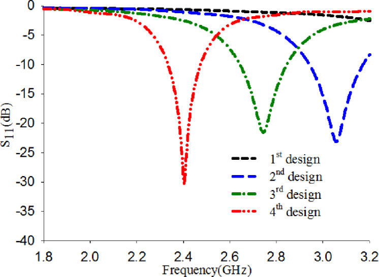
S11 of the evolution designs.

| Parameter | A | B | C | D | w | w1 | w2 | L | L1 | L2 | L3 | L4 | L5 | L6 | L7 | L8 | Lg |
| Value | 16 | 20.4 | 10.6 | 14 | 30 | 16 | 2.295 | 50 | 16.6 | 9.8 | 5.7 | 4.97 | 1.65 | 2 | 2.65 | 9 | 17.4 |
The EBG unit cell structure evolved from a conventional mushroom-like EBG, as depicted in Fig 3(A). The dispersion diagram technique is used to analyze the EBG unit cell [35]. The desired bandgap is obtained with an overall dimension of 23×23×0.7 mm3, as shown in Fig 3(B). However, the existence of vias while using fabric material makes the process of fabrication more complicated. Therefore, vias are removed and becomes vialess (uni-planar). The vialess unit cell with the same dimension of exciting vias as depicted in Fig 4(A) is simulated, but the obtained bandgap does not cover the desired band 2.4 GHz as shown in Fig 4(B). The absence of vias caused the bandgap to shift to higher frequency bands, as mention in [36].
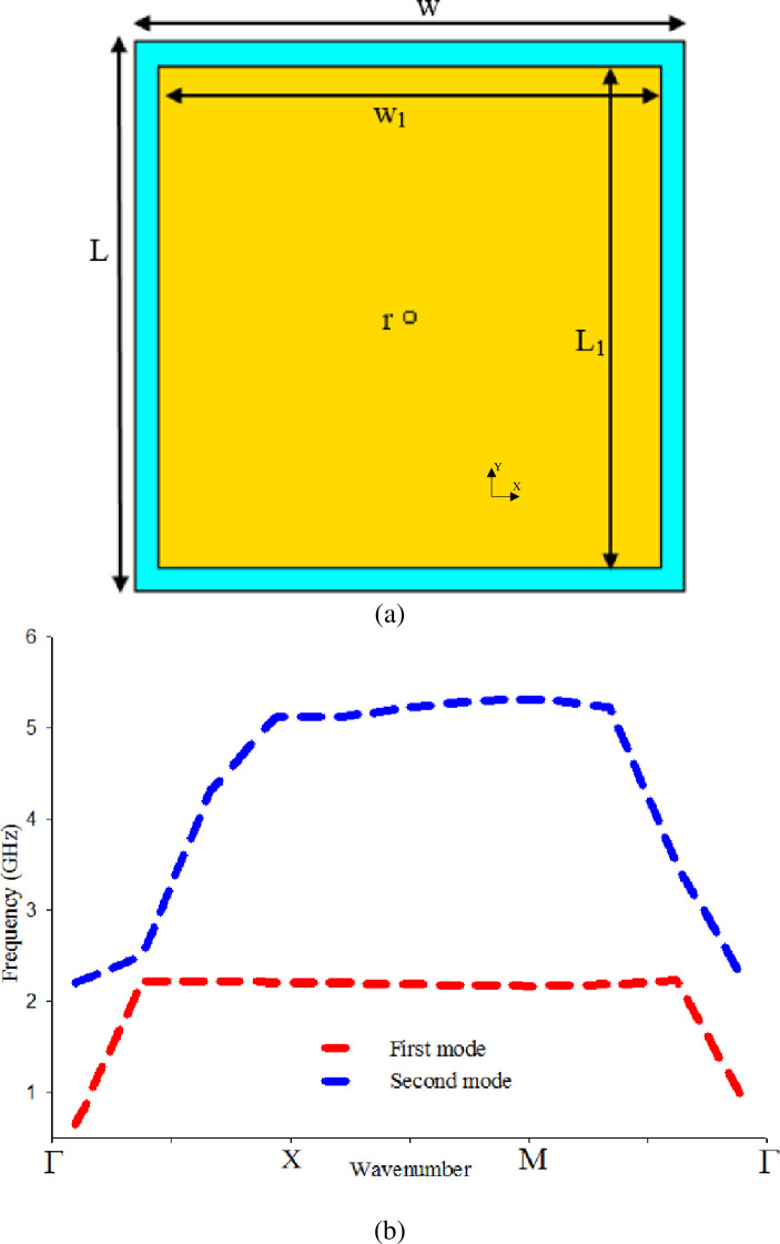
(a) Mushroom-like EBG unit cell, and (b) Bandgap characteristics of (a).
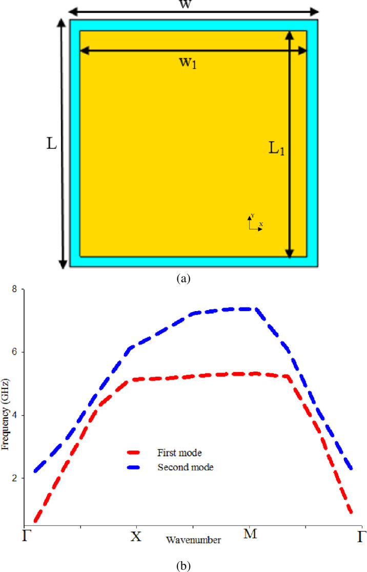
Vialess square patch EBG unit cell, and (b) Bandgap characteristics of (a).
A significant benefit of the “uni-planar” EBG design is the elimination of the vertical via. This makes the fabrication process easier and compatible with millimeter-wave and microwave circuits. However, the complex EBG structure possesses its challenges in prototyping even if vias have been eliminated. Producing this from fabric materials makes the task even more difficult and might lead to inaccuracy. One of the motivations is to minimize design complexity while gaining maximum output from the EBG. Hence, the vialess EBG unit cell is modified as depicted in Fig 5(A). The proposed design reveals the desired bandgap cover of 2.4 GHz, as presented in Fig 5(B). Without the existing on the vias, the proposed crossed strip lines could increase the inductance [37] and control the bandgap with a simple structure that can be easily fabricated using fabric materials. The optimum dimensions are tabulated in Table 2.
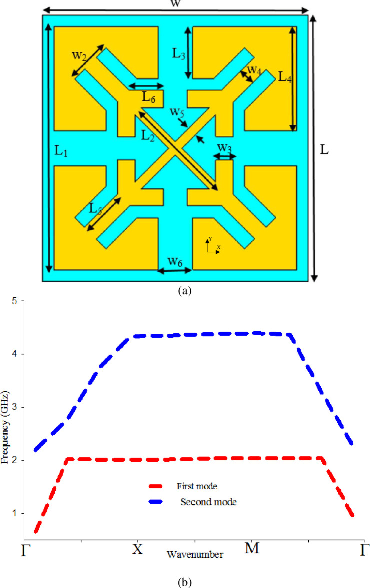
(a) Vialess proposed EBG unit, and (b) Band-gap characteristics of the proposed vialess EBG unit cell.
| Parameter | w | w1 | w2 | w3 | w4 | w5 | w6 | r | L | L1 | L2 | L3 | L4 | L5 | L6 |
| Value | 23 | 21 | 3.8 | 1.5 | 1.4 | 1 | 3 | 0.25 | 23 | 21 | 10 | 4.5 | 9 | 4 | 3 |
The reference antenna was placed on a 2×2 EBG array, as revealed in Fig 6(A). A 1 mm foam layer is inserted between the two layers to prevent any connection that causes a short circuit. The overall size of the integrated antenna with EBG, including the foam, is 50×50×2.4 mm3. The S11 of reference antenna with and without EBG is depicted in Fig 7. It is seen that the reference antenna alone shows an operating frequency covered the 2.4 GHz. However, adding EBG to the reference antenna revealed that the S11 is shifted from 2.4 GHz to 1.96 GHz. In order to obtain the desired band covering 2.4 GHz, the reference antenna and the EBG ground plane dimensions are modified as shown in Fig 6(C), 6(E) and 6(F). The optimum dimensions are tabulated in Table 3. This modification shows that the modified antenna's size can be reduced by 60% compared to the reference antenna.
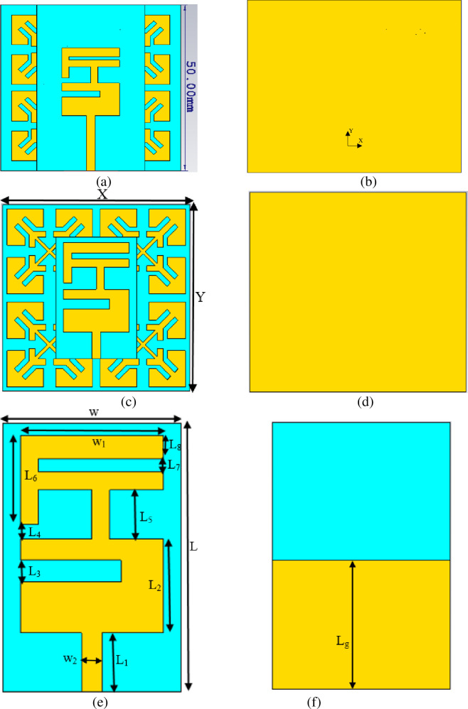
(a) Front view of the reference antenna with EBG, (b) Back view of the reference antenna with EBG, (c) Front view of the modified antenna with EBG, (d) Back view of the modified antenna with EBG, (e) Front view of Modified antenna, and (f) Back view of Modified antenna.
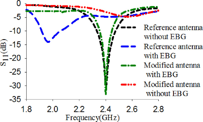
S11 of the reference antenna alone, the integrated reference antenna with EBG, the modified antenna with EBG, and the modified antenna alone.
| Parameter | w | w1 | w2 | L | L1 | L2 | L3 | L4 |
| Value | 20 | 16 | 2.295 | 30 | 6.6 | 10.5 | 2.4 | 1.6 |
| Parameter | L5 | L6 | L7 | L8 | Lg | X | Y | |
| Value | 5.475 | 10 | 1.47 | 2.65 | 14.5 | 46 | 46 |
To further confirm the role of the EBG in reducing the size of the reference antenna, the surface current is simulated at 2.4 GHz for the modified antenna alone, and the modified antenna with EBG as illustrated in Fig 8. The results in Fig 8(A) show that when the modified antenna is alone, less current is concentrated on the radiating patch. This is due to the modified antenna alone does not resonate at 2.4 GHz. However, the modified antenna's surface current with EBG shows a maximum concentrated current density mainly located on the radiating elements. This observation indicates that EBG could contribute as a radiator and reduce the size of the reference antenna.
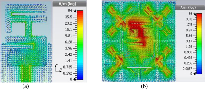
Surface current (a) Modified antenna alone, (b) Reference antenna, and (c) Modified antenna with EBG.
The reference antenna and the modified antenna with EBG were modeled, and their performance was predicted using CST Microwave Studio [38]. Fig 9 describes the simulated and measured S11 results of the reference antenna and the modified antenna with EBG. This demonstrates that the measured results are in good agreement with the simulated results. Very slight differences can be noticed, and these may be attributed to fabrication errors and soldering tolerance.
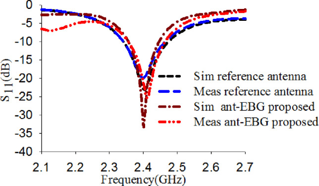
S11 result of the reference antenna alone, and integrated modified antenna with EBG.
Fig 10 presents the normalized numerical and experimental radiation patterns of the reference antenna and the modified antenna with EBG along the x-z and y-z plane at 2.4 GHz. It can be seen that the reference antenna along the x-z plane has maximum radiation in the ±z-direction while an omnidirectional along the y-z plane. The maximum radiation in the negative z-direction is not preferred for wearable antennas operating close to the body. This is due to the radiation towards the body that may present a health risk factor when it is irradiated over prolonged periods [15]. A directional radiation pattern is preferred when the antenna operates with other devices far away from the body. However, the modified antenna with EBG shows directional radiation by reflecting the back lobe toward the +z-direction along both planes x-z and y-z. As a result, the radiation towards the body is reduced by 12.3 dB. Furthermore, the modified antenna shows a better gain of 7.2 dBi than the reference antenna with a gain of 2.2 dBi. Also, it reveals an efficiency of 74.8%.
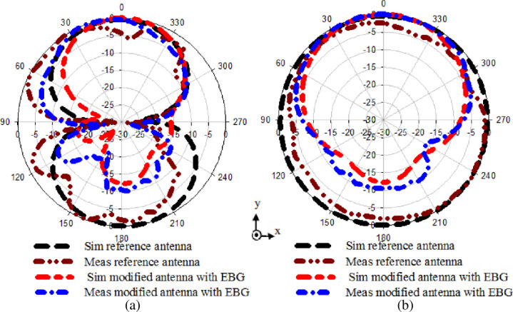
Normalized radiation performance of the reference antenna alone, and integrated modified antenna with EBG vialess (a) x-z plane, and (b) y-z plane.
The bending analysis of the proposed antenna over foam cylinder along the x-z plane and y-z plane for varying diameters (70 mm, 80 mm, 100 mm, 140 mm) were experimentally carried out to ensure that the performance under bending condition still satisfies the wearable application. In this study, the diameters were chosen to approximate the arm and leg of the human body. The results are depicted in Fig 11. It shows that the bending has nearly no effect on the modified antenna with EBG performance. It is realized that although the operating frequency band and the resonance frequency are slightly shifted, the S11 still maintains the bandwidth covering the 2.4 GHz ISM band when the bending diameter (d) is varied in the range from 70 to 140 mm.
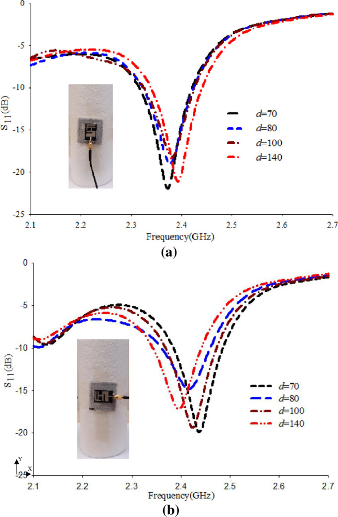
S11 performance based on bending along (a) x-z plane, and (b) y-z plane.
The modified antenna's normalized radiation pattern performance with EBG was also experimentally investigated along x-z and y-z plane with a diameter of d = 140 mm. The radiation patterns are tested at 2.4 GHz, as revealed in Fig 12, and demonstrates acceptable radiation patterns with good gain around 6.4 dBi, FBR around 8 dBi, and efficiency around 66%. This investigation demonstrates that our structure is highly conformal and a suitable candidate for body-worn devices.
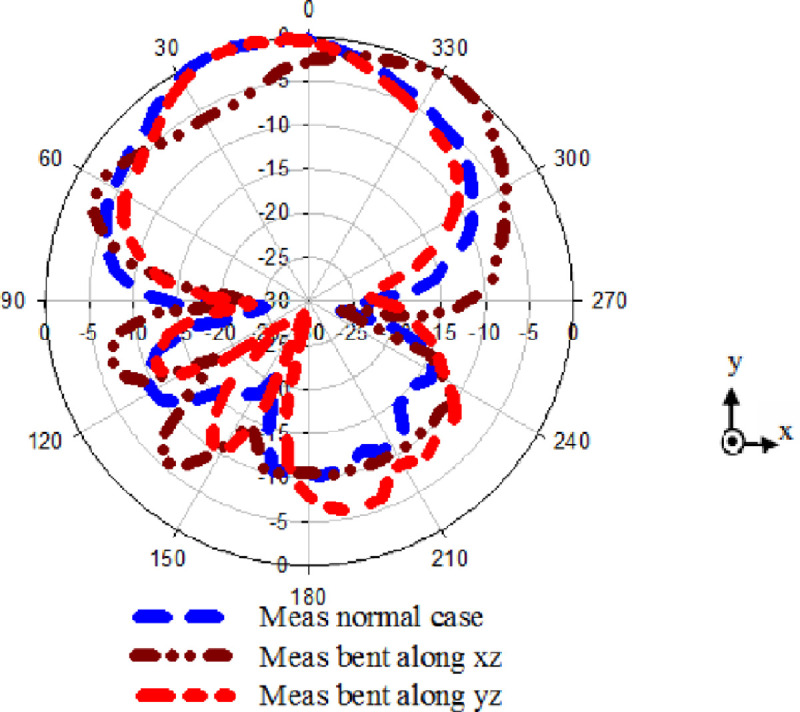
Radiation pattern performance based on bending at diameter d = 140 along x-z and y-z planes.
The Human Research Ethics Committee of Universiti Tun Hussein Onn Malaysia waived the need for ethical approval. The participant was voluntary and gave verbal informed consent.
The reference antenna and the modified antenna with EBG have been simulated and measured on the body to validate their operational performance due to the body's high dielectric. Two parts of the body, the chest, and the arm were chosen for the numerical and the experimental investigation. The selection of these two parts is to evaluate the proposed design in terms of bending (around the arm) and normal case (mounted over the chest). This is to ensure the functionality of the proposed design in both cases when loaded on human tissues. The models are developed using CST for numerical studies. The cylinder with a diameter of 80 mm and 150 mm length was developed to imitate the arm shape Fig 13(A) [5, 11]. A square shape with a length and width of 150 mm and a thickness of 40 mm was designed to emulate the chest shape as depicted in Fig 13(B). Each model consists of four layers: fat, bone, skin, and muscle, and their corresponding typical conductivity, thickness, mass density, and permittivity values for each layer are summarized in Table 4 [5, 11].

Developed human models (a) Arm, and (b) Chest.
A volunteer male weighing 79 kg and 160 cm tall are used for experimental studies to verify the simulated performance. The design was bent on the arm and mounted on the chest, as shown in Fig 14. The arm has a diameter of 80 mm, which is equivalent to the developed arm. This study gives extra credibility to work by adopting a real human body instead of simulated models.
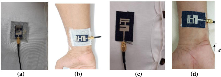
(a) Proposed design on chest, (b) Proposed design on arm, (c) Reference antenna on chest, and (d) Reference antenna on arm.
As shown in Fig 15(A), the reference antenna leads the S11 to shift from 2.4 GHz to a lower band for both arm and chest case. This is because the human body acts as an additional complex substrate layer that has high permittivity. Therefore, placing the reference antenna directly on the human body results in a severe impedance mismatch of the antenna. In the case of integrating the modified antenna with EBG, the required spectrum bandwidth is achieved as described in Fig 15(B). This is because the EBG shields the antenna from the body effects. The measurement results are almost identical to the simulation results. Hence, the modified antenna with EBG is a well-suitable candidate for wearable applications, including medical devices.
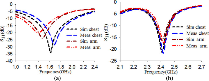
S11 performance of designs placing on the chest and the arm (a) Reference antenna and (b) Proposed design.
Further investigation is conducted to analyze the worst-case scenario of varying the dielectric constant (εr) of the human model tissue on the proposed design's performance in terms of its S11 stability. This investigation is carried out to ensure the proposed design's robustness and functionality when loaded on a high dielectric constant [39]. Therefore, we assume that the skin layer has values in the range of 10 to 150. The design was placed directly on the model. The S11 of the reference antenna and the modified antenna with EBG were obtained for different permittivity values (εr), namely 10, 30, 70, 110, and 150, as shown in Fig 16. The results showed that when the antenna alone, the S11 was shifted to the lower band and did not operate at the desired band. Meanwhile, with EBG, the S11 is maintained at the desired band. This proves that the EBG act as isolation between the body and the antenna. It also demonstrates its robustness and functionality even if it loaded at a high dielectric constant.
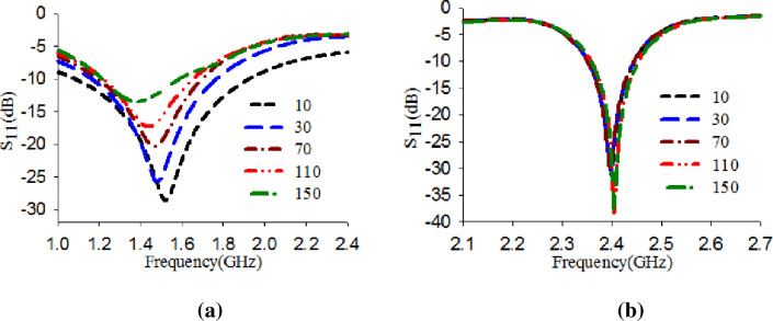
S11 performance with varying the dielectric constant of the skin layer (a) Reference antenna and (b) Proposed design.
Fig 17 displayed the normalized radiation patterns’ performances when the antenna was loaded on the chest and arm. The result illustrates that the radiation properties of the reference antenna is greatly influenced and become more directive when placed on the human body because of its high permittivity compared to the fabric substrate of the reference antenna, as shown in Fig 17(A). This indicates that the body absorbed the power, which could cause a health risk while placing the modified antenna with EBG on the chest and arm reveal a reasonable radiation characteristic as shown in Fig 17(B). It can maintain its shape pattern as free space with the minor difference that does not affect the radiation performance.
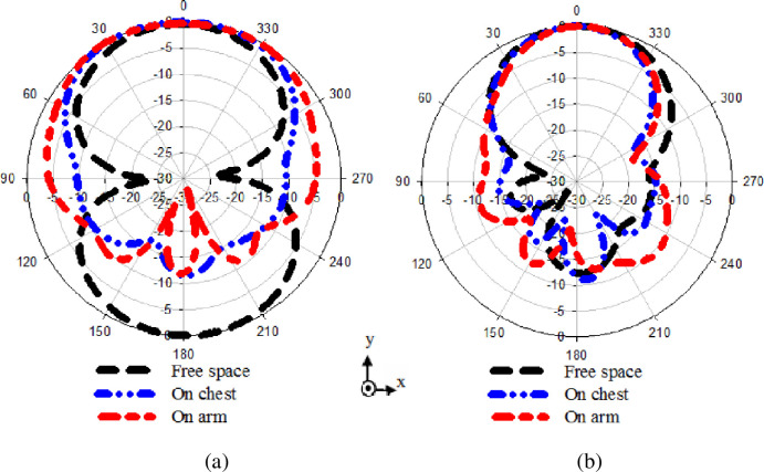
Radiation pattern performance placing on chest and arm (a) Reference antenna, and (b) Proposed design.
SAR is a standard measure of power deposition in the human tissues per unit mass. Therefore, its assessment is vital to ensure that safety limits are met. The same model used in section 5.1 is used for numerical SAR analysis to verify the performance. According to the Federal Communication Commission (FCC), the 1 g averaged SAR value should not exceed 1.6 W/kg [39]. The following equation relates SAR with the applied input power used to calculate the SAR:

The SAR evaluation is conducted using the IEEE C95.1 standard available in the CST MWS software. The input power for the calculation is taken as 100 mW [5, 11, 12]. Table 5 summarizes the SAR calculation results for both designs, taken for different scenarios, including cases where the antenna is mounted on the arm and the chest. The SAR calculation was also performed with antenna placements at 0 mm (touching the skin), 1 mm, and 3 mm away from the body part. The table shows that, for the antenna without EBG, the SAR value averaged over 1g decreased with increasing distance between the antenna and the phantom model. However, these SAR values still exceed safety limits governed by the FCC standard throughout all antenna placements.
| Distance from the phantom (mm) | Antenna w/o EBG | Antenna w/EBG | ||||
|---|---|---|---|---|---|---|
| On arm | On chest | On arm | On chest | |||
| y-axis | x-axis | y-axis | x-axis | |||
| 0 | 13.6 | 11.2 | 7.41 | 0.132 | 0.050 | 0.058 |
| 1 | 6.05 | 5.98 | 5.7 | 0.054 | 0.036 | 0.037 |
| 3 | 5.22 | 5.7 | 4.36 | 0.047 | 0.025 | 0.028 |
Although the antenna was 3 mm distant from the human body, it still shows a maximum SAR of 5.22 W/kg averaged over 1g. This is due to its omnidirectional radiation characteristic [5, 11]. When integrated with EBG, a substantial drop in the maximum SAR value averaged over 1 g is realized, thus complying with the safety standards, even when the antenna integrated with EBG is directly placed on the skin (touching the skin) as shown in Fig 18. The reduction is more than 95% compared to the proposed reference antenna without the EBG, showing the superiority of the antenna when incorporated with the EBG.
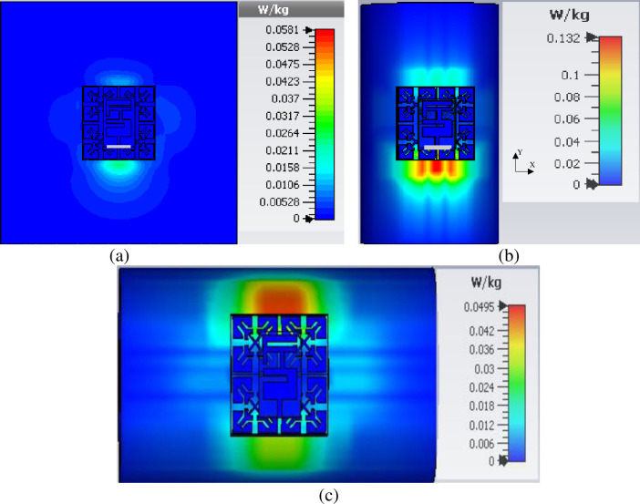
SAR values of proposed design when touch the skin over 1 g (a) On chest, (b) On arm y-axis, and (c) On arm x-axis.
The SAR also was evaluated by changing the skin layer electrical properties to analyses the worst-case scenario of SAR. The result of the antenna with and without EBG is tabulated in Table 6. It is observed that for all analyzed cases, namely for εr = (10, 30, 70, 110, 150), when the antenna alone, the SAR values exceed the safety limit set by FCC. However, when integrating the EBG structure with the antenna, the SAR values are much lower than the FCC limits for all analyzed cases. These simulated results were compared with other similar published works as tabulated in Table 7. They all seem very close values to the literature. Table 7 depicts the comparison of the proposed wearable antenna design's performance with other backed two years of published works. As can be seen, the proposed design outperforms the other reported work based on overall size, FBR, gain, and comparable performance in terms of efficiency, SAR, and the unit cell number.
| Permittivity Design | 10 | 30 | 70 | 110 | 150 |
| Antenna w/o EBG | 11 | 10.1 | 8.17 | 8.95 | 6.89 |
| Antenna w/EBG | 0.037 | 0.030 | 0.022 | 0.017 | 0.016 |
| Ref | Year | Efficiency (%) | Gain (dBi) | SAR W/kg | FBR (dB) | No. of unit cell | Overall size (mm3) | Substrate type |
|---|---|---|---|---|---|---|---|---|
| [29] | 2018 | 71 | 7.3 | 0.230 | 17 | 3×3 | 81×81×4 | Fabric |
| [21] | 2019 | 49 | 8.3 | - | - | - | 70×85×6 | Felt |
| [23] | 2020 | 70.7 | 6.56 | 0.612 | - | 3×3 | 60×60×8.5 | PDMS |
| [15] | 2020 | - | 6.45 | 0.983 | 16 | 2×2 | 60×60×2.4 | Fabric |
| [7] | 2020 | 44.39 | 4.06 | 0.521 | - | 1×2 | 50×25.7×5 | Felt |
| [30] | 2020 | - | 1.94 | 0.111 | 12 | 3×3 | 85.5×85.5×5.28 | Felt |
| [22] | 2020 | 61 | 6.19 | - | - | 4×3 | 145×112×3.424 | Jeans |
| [24] | 2020 | 74.8 | 6.51 | 0.22 | 11.4 | 2×2 | 56×56×6 | Ultralam850,Felt |
| This work | - | 74.8 | 7.2 | 0.042 | 12.2 | 2×2 | 46×46×2.4 | Fabric |
A compact fully fabric antenna with a miniaturized EBG structure for wearable applications was successfully designed and experimentally tested. In contrast to earlier documented EBG backed antenna designs, the proposed EBG behaves as shielding from the antenna to the human body, reduces the size, and acts as a radiator. It also shows band-gap features without requiring vias. The miniaturized EBG array in the proposed design has contributed to enhancing the radiation efficiency and providing isolation between the antenna and human tissues. The antenna’s behavior under flexing and loading on a human body was experimentally investigated. The measured performance of the proposed antenna-EBG structure compares favorably to the most recent reported results. The experimental results show that the antenna-EBG integration achieves a gain of 7.2 dBi, an efficiency of 74.8%, and an FBR of 12.2 dB. Furthermore, the specific absorption rate (SAR) shows a reduction of more than 95% compared to the antenna alone and complies with the FCC standard. Hence, the presented incorporated antenna with EBGs is a well-suitable candidate for wearable applications, including medical devices.
1
2
3
4
5
6
7
8
9
10
11
12
13
14
15
16
17
18
19
20
21
22
23
24
25
26
27
28
29
30
31
32
33
34
35
36
37
38
39
 Via-less electromagnetic band-gap-enabled antenna based on textile material for wearable applications
 Facebook
 Twitter
 Linkedin
 Whatsapp

