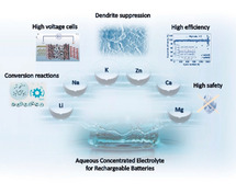
 Challenges and Strategies for High‐Energy Aqueous Electrolyte Rechargeable Batteries
Angewandte Chemie (International Ed. in English)


- Altmetric
Aqueous rechargeable batteries are becoming increasingly important to the development of renewable energy sources, because they promise to meet cost‐efficiency, energy and power demands for stationary applications. Over the past decade, efforts have been devoted to the improvement of electrode materials and their use in combination with highly concentrated aqueous electrolytes. Here the latest ground‐breaking advances in using such electrolytes to construct aqueous battery systems efficiently storing electrical energy, i.e., offering improved energy density, cyclability and safety, are highlighted. This Review aims to timely provide a summary of the strategies proposed so far to overcome the still existing hurdles limiting the present aqueous batteries technologies employing concentrated electrolytes. Emphasis is placed on aqueous batteries for lithium and post‐lithium chemistries, with potentially improved energy density, resulting from the unique advantages of concentrated electrolytes.
A matter of concentration: The latest ground‐breaking advances and strategies of using concentrated electrolyte for aqueous batteries, are discussed. Emphasis is placed on aqueous batteries for lithium and post‐lithium chemistries, with improved energy density, resulting from the unique properties of salt‐concentrated electrolytes.
Introduction
The transition towards a sustainable energy future relies on the development of efficient energy storage technologies. Electrochemical energy storage systems (EESSs) are considered among the best choices to store the energy produced from renewable resources, such as wind, solar and tidal power on the short‐ (daily) and mid‐term (weekly) scale. [1] The diverse range of chemistries employed in EESSs defines the characteristics of the final system, thus enabling the obtainment of a plethora of systems with specific performance requirements for integration of renewable energy at different levels of the grid, enabling stabilization, flexibility, and a secure energy supply.
Among the various EESSs, rechargeable batteries, especially lithium‐ion batteries (LIBs) are seen as the key technology to rapidly decarbonize the energy transportation scenario and, on a longer time‐scale, the small‐ to mid‐size stationary energy storage. Within the past thirty years, LIBs have dominated the market for portable electronics and are currently conquering the market of hybrid and electric vehicles (EVs). Such a rapid development has been certainly driven by their attractive properties. LIBs are light, compact, efficient and exhibit the highest volumetric and gravimetric energy among all commercial batteries. However, some intrinsic characteristics make them less feasible for large‐scale stationary energy storage applications, where cost, safety, and cycle life become relatively more important than energy density. In addition, safety concerns arise from abuse conditions generally caused by mechanical, thermal or electrochemical stress. [2] The flammability of the organic solvent‐based electrolyte and the instability of the electrode/electrolyte interfaces (EEIs) are certainly other critical issues. Several solutions have been proposed so far to overcome the safety issues of LIBs, such as the implementation of redox shuttle additives for overcharge protection, flame retardant additives, or the use of less volatile electrolytes such as ionic liquids, [3] polymer and/or inorganic solid electrolytes. [4]
An interesting approach to sidestep the cost and safety issues consists in using aqueous electrolytes. In fact, aqueous rechargeable batteries (ARBs) attract great interest due to their intrinsic safety when compared with non‐aqueous systems since, in spite of their limited energy density performance due to the lower operating voltage range, the intrinsic non‐flammability of aqueous electrolytes represents a great advantage. [5] Moreover, the water solvent and salts employed, commonly nitrates and sulfates, are likely to substantially reduce the cost of the electrolytes. [6] In addition, the high ionic conductivity of aqueous solutions, which is two orders of magnitude higher than that of organic solvent‐based electrolytes, enables high power capability. All these characteristics make ARBs very promising for large‐scale energy storage.[ 5 , 7 ]
Since Dahn et al. in 1994 reported an ARMB employing LiMn2O4 as cathode, VO2(B) as anode, and a 5 mol L−1 aqueous solution of LiNO3 as electrolyte, [8] aqueous rechargeable metal‐ion batteries (ARMBs) are considered especially attractive for large‐scale or stationary energy storage application in view of their safety, sustainability and low economic impact. [9] The economic impact is one of the key factors to enable the next generation sustainable technologies. A report recently published by Pacific Northwest National Laboratory evaluated cost and performance parameters of different battery technologies. [10] It is reported that the capital cost prediction for 2025 is 289, 220 and 393 $ kWh−1 for lithium‐ion, lead acid and redox flow batteries, respectively. In 2018 the estimated capital cost for lead acid batteries, the most conventional aqueous system, [11] was about 260 $ kWh−1. Interestingly, AQUION Inc. commercialized an Aqueous Hybrid Ion (AHI™) technology, employing a Na‐based aqueous electrolyte, manganese oxide cathode, carbon–titanium phosphate composite anode, and cotton as separator, i.e., using only abundant and non‐toxic materials, targeting a projected capital cost of less than 250 $ kWh−1 at the pack level. [12]
These ARMBs share the electrochemistry with conventional alkali‐ion battery systems containing organic‐based electrolytes. However, further improvements on the energy density and lifespan are still needed for the implementation of ARMB in grid‐levelling and large‐scale energy storage. The main limitation is certainly related to the narrow electrochemical stability window (ESW) of the aqueous electrolyte, beyond which, e.g., H2O (ESW of 1.23 V), it can be decomposed into H2 and O2. The occurrence of these side reactions limits the choice of electrode materials with working potentials within the H2 and O2 evolution potentials, thus directly affecting the cell energy and power densities. Other common drawbacks affect the choice of the electrode materials, e.g., their solubility in water‐based electrolytes and the occurrence of severe side reactions upon cycling.[ 6 , 13 ]
Nonetheless, the ever‐growing knowledge and understanding of the reaction mechanisms and operating condition of materials for application in LIBs represent an undoubtable advantage, offering an excellent starting launch pad for the development of the innovative, sustainable, and harmless ARMBs. Several promising results have been achieved so far, [14] especially associated to the mitigation of O2 evolution reaction and the identification of stable electrode materials undergoing limited side reactions as well as dissolution. Although lead–acid cells are the most recognizable ARMBs still representing a major proportion of the global battery market, [11] the commercial feasibility of competitive ARMBs is still far to be reached. Despite the recent progresses on the development of electrode materials,[ 13b , 15 ] the ESW of aqueous electrolytes remains still too narrow. An effective strategy to increase the ESW of such electrolytes involves tuning the alkalinity of the solutions in order to shift the H2 evolution reaction (i.e., water reduction) towards lower potentials. However, having in mind the Pourbaix diagram, this corresponds also to lowering the anodic stability of the electrolyte. Recently, a new proposed concept, that is, “water‐in‐salt” electrolytes (also known as WiSE) demonstrated to be able to efficiently expand the ESW by forming a passivating layer on the electrodes’ surface further suppressing H2 evolution. [16] Following this approach, in principle similar to the solid electrolyte interphase (SEI) in LIBs, [17] but very different in nature, the ESW of the aqueous electrolyte has been enhanced to almost 3 V, enabling a 2.3 V Li‐ion cell. [16]
In this Review, the progress of using concentrated electrolytes in rechargeable aqueous batteries is comprehensively discussed, highlighting their unique electrochemistry and summarizing the latest advancements. The critical role of hybridization strategies for the rational electrolyte design and battery chemistry innovation is discussed, showing as the energy density of such a technology can be substantially improved.
Electrochemistry in Concentrated Aqueous Electrolytes
Studies devoted to concentrated organic electrolytes for LIBs started in the early 80’s with the pioneering work of McKinnon on the co‐intercalation suppression of propylene carbonate (PC) in layered ZrS2 electrodes using a saturated solution of LiAsF6 in PC. [18] Following this discovery, in 2003 Ogumi et al. demonstrated the possible use of PC‐based concentrated electrolyte with graphite anodes, in spite of the well‐known issue associated with the co‐intercalation of PC resulting in graphite exfoliation. [19]
In the last decade, several studies have been carried out reporting the interesting behavior of concentrated electrolytes, [20] presenting improved stability of the lithium/electrolyte interface and interphase, [21] suppressing the anodic dissolution of the aluminum current collector,[ 20c , 22 ] and improving the oxidative stability of the solvent, thus enabling the operation of high voltage cathode materials in lithium metal batteries. [23]
Among the disadvantages of this class of electrolytes it is worth mentioning that, as widely known, increasing the salt concentration leads to decreased ionic conductivities. Indeed, high viscosity and reduced ionic conductivity may represent a drawback, however, additional unique properties have been reported for concentrated aqueous electrolytes. In fact, in diluted aqueous solutions ions are fully coordinated by water molecules, thus the dominant species are solvent‐separated ion pairs (SSIPs) and free solvent molecules. By increasing the salt concentration, e.g., achieving molality values higher than 9 m (i.e., 9 mol of salt per kg of solvent), the formation of contact ion pairs (CIPs) and aggregated cation–anion pairs (ACAPs) is induced due to the reduced availability of solvent molecules. The different solvation structures mentioned above are illustrated in Figure 1 a. The unique cation–anion coordination affects the electrolyte/electrode interface and, especially, the formation of the interphase, triggering the mechanism of anion‐derived SEI chemistry. [23f] In a conventional alkali metal‐ion battery employing organic‐based electrolytes, the performance is highly dependent on the stability of the electrode/electrolyte interfaces, especially at the anode where an SEI is inevitably formed due to electrolyte reduction. This is due to the rather low operating voltage of the anode, which is electrochemically active beyond the ESW of the electrolyte. [24] On the other hand, the SEI formation mechanism in aqueous electrolytes is rather unexplored, although it has been proposed that its properties are strongly affected by the salt concentration, as for organic‐based electrolytes. [23e]

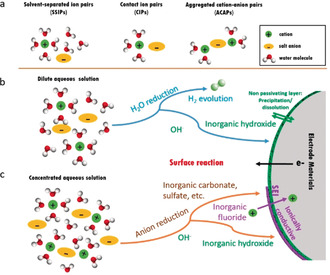
(a) Representative cation solvate species in aqueous solution, and schematic illustrations of the electrolyte reduction for the SEI formation in diluted (b) and concentrated (c) aqueous solutions for rechargeable metal‐ion batteries.
The SEI concept can also be transferred into aqueous media. In a dilute solution, the decomposition of water will occur when discharging to low voltage, resulting in the concurrent formation of OH− and H2 evolution. It is expected that side reactions with the hydroxide groups or O2 dissolved in water would strongly corrode the electrode surface. The resulting products may precipitate on the electrode surface, preventing ion diffusion and consequently leading to capacity fading and inferior power capability, as indicated in Figure 1 b. However, due to the scarcity of water molecules in highly concentrated electrolytes, the anions present in the CIPs and ACAPs are strongly involved into the SEI layer formation. This results in the formation of an SEI altering Li+‐solvation sheath structure as demonstrated by the recent ground‐breaking work of Suo et al. [16] Thus, the SEI formation process strongly depends on the properties of the anion. The most commonly employed anions for battery electrolytes are fluorine‐based compounds, which have a beneficial impact on the formation of ionically conductive decomposition products in the SEI of non‐aqueous electrolytes. [25] Similar to the case of organic based electrolytes, several key factors have been identified as responsible for the formation of a stable aqueous SEI, including the salt concentration, chemical structure of salt anion, solubility of the reduction products in aqueous media, and the formation condition. [26] Grimaud et al. demonstrated that hydroxides generated from the H2 evolution reaction can chemically react with the TFSI anions and catalyze the formation of a fluorinated SEI that prevents further water reduction. [27] Thus, the formation of SEI in WiSE can be attributed to both the solvent and salt decompositions. Indeed, fluorine‐rich interphases serve as electron barrier preventing further electrolyte reduction while still allowing for cation conduction (as shown in Figure 1 c). On the other hand, the absence of organic compounds results in the formation of a thin and robust inorganic SEI films significantly enhancing the electrodes stability. [23e]
Although the highest occupied molecular orbital (HOMO) and lowest unoccupied molecular orbital (LUMO) have been widely used to explain the ESW of electrolytes in batteries, HOMO and LUMO are concepts derived from the electronic structure of isolated molecules and their energy levels. Thus, a translation of their values to redox potentials where either the solvent or the electrolyte oxidation/reduction takes place is not straightforward. Indeed, solvents that appear to be stable in terms of HOMO and LUMO energies, can participate into oxidation and reduction processes involving the salt(s) and/or reactive surface sites of the electrodes. [28] For example, from an electronic structure perspective, the band gap of pure water is 8.7 eV ±0.6 eV. However, the ESW of liquid water is only 1.23 V, being limited (at pH 7) by the hydrogen evolution (−4.02 eV) and oxygen evolution (−5.25 eV) reactions. [29] Therefore, the reduction and oxidation potentials are the determining parameters for the correct identification of the aqueous electrolytes ESW. [28] Figure 2 a presents a schematic of the energy levels in the electrodes and the aqueous electrolyte of an electrochemical cell. The energy separation E g between the reduction and oxidation potential is the thermodynamic stability window of the electrolyte. The two electrodes are electronic conductors with electrochemical potentials ũ and ũ . An anode with ũ above the hydrogen evolution potential will reduce water unless a passivation layer creates a barrier to electron transfer from the anode to the electrolyte. On the other side, a cathode with ũ below the oxygen evolution potential will oxidize water unless a passivation layer blocks electron transfer from the electrolyte to the cathode. Therefore, the open‐circuit voltage of the cell (E cell) is constrained as reported in Equation 1:
![(a) Schematic open‐circuit energy diagram of an aqueous electrolyte. −e[E
effective reduction] and −e[E
effective oxidation] are the effective reduction and oxidation energies of the electrolyte. E
g is the electrolyte's electrochemical stability window. ũ
e-,anode
and ũ
e-,cathode
are the electrochemical potentials of anode and cathode, respectively. (b) Illustration of the expanded electrochemical stability window for concentrated aqueous electrolytes. Adapted and modified from Ref. [15].](/dataresources/secured/content-1765840379248-02c13031-df47-4fd4-bf05-763983f4e76b/assets/ANIE-60-598-g005.jpg)
(a) Schematic open‐circuit energy diagram of an aqueous electrolyte. −e[E effective reduction] and −e[E effective oxidation] are the effective reduction and oxidation energies of the electrolyte. E g is the electrolyte's electrochemical stability window. ũ and ũ are the electrochemical potentials of anode and cathode, respectively. (b) Illustration of the expanded electrochemical stability window for concentrated aqueous electrolytes. Adapted and modified from Ref. [15].
As presented in Figure 2 b, the ESW of aqueous electrolytes can be widen by increasing the salt concentration and/or favoring the formation of stable passivating layers at the EEIs. Early research has shown that a saturated LiNO3 aqueous solution presents an ESW of 2.8 V, i.e., far beyond that of conventional aqueous electrolytes.[ 14e , 30 ] However, cells employing this electrolyte show fast capacity fading with low discharge capacity, indicating the poor ability of NO3 − anion to form stable SEI layers preventing the electrodes and electrolyte degradation. Additionally, even in less concentrated solution, suppressed hydrogen and oxygen evolution is observed, most likely resulting from the reduced water activity when coordinated to cations and the inner Helmholtz layer increasingly populated by anions. [22] The most diluted aqueous electrolytes present ESWs up to 2.0 V, i.e., 50 % larger than pure water (1.23 V). ESW higher than 2.0 V can be achieved by further increasing the salt concentration due to the reduced water activity and modulated redox potentials (attributed to the cation redox activity change in the solution according to the Nernst equation), and also to the kinetically suppressed hydrogen and oxygen evolution. [16] Overall, the salt concentration plays a significant role in the ESW of aqueous electrolytes, which, in turn, determines the electrode materials and the energy output of aqueous batteries.
Aqueous Lithium Batteries
The unique electrochemistry of concentrated aqueous electrolytes enables to overcome several challenges toward high energy aqueous batteries, as summarized in Figure 3. These include: (1) limitation of using low potential anode within narrow ESW of aqueous electrolyte; (2) SEI formation in aqueous environment; (3) implementation of conversion chemistry with high capacity; (4) elimination of parasitic reactions of cathode materials and current collectors, inducing inferior cycling stability; and (5) low cost and sustainable alternative battery technologies. In this section a comprehensive review of various lithium batteries employing aqueous electrolytes (ALBs) is presented. The most recent advances on ALBs are discussed with a particular focus on the unique chemistries resulting from the use of concentrated aqueous electrolytes.
![Advances of rechargeable batteries achieved by the concentrated aqueous electrolyte. The insets enclose the representative advanced functions in batteries: anode protection (reproduced from Ref. [31]), fluorinated interfaces (reproduced from Ref. [32]), stable current collector (reproduced from Ref. [33]), post‐lithium chemistries, sulphur conversion (reproduced from Ref. [34]), reversibility of Li/O2 cells (reproduced from Ref. [35]), and dendrite suppression of Zn (reproduced from Ref. [36]).](/dataresources/secured/content-1765840379248-02c13031-df47-4fd4-bf05-763983f4e76b/assets/ANIE-60-598-g006.jpg)
Advances of rechargeable batteries achieved by the concentrated aqueous electrolyte. The insets enclose the representative advanced functions in batteries: anode protection (reproduced from Ref. [31]), fluorinated interfaces (reproduced from Ref. [32]), stable current collector (reproduced from Ref. [33]), post‐lithium chemistries, sulphur conversion (reproduced from Ref. [34]), reversibility of Li/O2 cells (reproduced from Ref. [35]), and dendrite suppression of Zn (reproduced from Ref. [36]).
Aqueous Li‐Ion Batteries (ALIBs)
The main driving force for the development of aqueous Li‐ion cells are safety and environmental concerns, both associated to the use of organic‐based electrolytes in conventional LIBs.[ 9 , 14d , 14e ] Among the electrode materials compatible with the use of aqueous electrolytes, insertion‐type compounds are the most investigated so far. Directly benefiting from the extended ESW of the highly concentrated electrolyte, some anode and cathode materials commonly employed in LIBs can also operate in the aqueous environment, as indicated in Figure 4 a. In 2015, the concept of “water‐in‐salt” electrolytes (WiSE), in contrast to typical “salt‐in‐water” electrolytes, was proposed showing extended ESW of 3.0 V (1.9–4.9 V vs. Li+/Li), i.e., far beyond water electrolysis. [16] This was achieved taking advantage of the high solubility of lithium bis(trifluoromethanesulfonyl)imide (LiTFSI) in water, i.e., up to 21 m of LiTFSI per kg of water corresponding to one mole of LiTFSI per 2.6 moles of water (LiTFSI⋅2.6 H2O). Such a concentrated solution well matches the definition of “water‐in‐salt”, since the number of H2O molecules involved in the Li+ solvation shell is lower than 2.6.
![Electrochemical stability windows of aqueous electrolytes and redox potentials of electrode materials in LIBs. (a) The typical redox potentials of a few anode and cathode materials used in commercial LIBs versus the Li+/Li potential scale. (b) Electrochemical stability window at pH 7 of aqueous electrolytes with different salt concentrations, i.e., pure water, 21 m LiTFSI (water‐in‐salt), and 27.8 m Li(TFSI)0.7(BETI)0.3 (hydrate melt) electrolytes. Adapted from Ref. [37].](/dataresources/secured/content-1765840379248-02c13031-df47-4fd4-bf05-763983f4e76b/assets/ANIE-60-598-g007.jpg)
Electrochemical stability windows of aqueous electrolytes and redox potentials of electrode materials in LIBs. (a) The typical redox potentials of a few anode and cathode materials used in commercial LIBs versus the Li+/Li potential scale. (b) Electrochemical stability window at pH 7 of aqueous electrolytes with different salt concentrations, i.e., pure water, 21 m LiTFSI (water‐in‐salt), and 27.8 m Li(TFSI)0.7(BETI)0.3 (hydrate melt) electrolytes. Adapted from Ref. [37].
As reported in Figure 4 b, the suppressed oxidization reaction of the LiTFSI‐based WiSE enables the use of various high voltage cathode materials used in LIBs. Mo6S8//LiFePO4, [38] Mo6S8//LiMn2O4, [16] Mo6S8//LiCoO2, [39] and Mo6S8//LiNi0.5Mn1.5O4 [40] cells have been fabricated using the above‐mentioned WiSE, generating output voltages of 1.2 V, 2.0 V, 2.5 V and 2.9 V, respectively. Although the WiSE‐based cells exhibit improved energy when compared to diluted aqueous electrolyte systems, e.g., the LiTi2(PO4)3//LiFePO4 cell employing Li2SO4 aqueous electrolyte offers a voltage output of only 1.0 V, further improvements on the delivered capacity and cycling stability are required to reach the theoretical values. [14d]
SEI for Low Potential Anode Materials
State‐of‐the‐art LIBs are close to attain their theoretical energy density. To enable even higher energy densities, high‐voltage (e.g., 5 V‐class) or high‐capacity (e.g., sulphur and/or lithium metal) materials are under intensive investigation. [41] However, with aqueous electrolytes the use of 5V‐class materials is even more challenging. Therefore, further improvements in ALIBs are achievable only enabling low‐voltage anode materials, via the formation of a properly designed electrode/electrolyte interphase kinetically hindering H2 evolution.
As it is known from non‐aqueous LIBs, the formation of an efficient SEI layer enables the operation of anode materials outside the electrolyte's ESW. [42] In concentrated aqueous electrolytes, the high salt concentration leads to a decrease of free water molecules resulting in the reduction of their electrochemical activity. However, besides the use of highly soluble lithium salts, reduced water molecules’ activity can be achieved by dissolving a second salt characterized with high solubility and similar chemical properties. A mixture of LiTFSI and lithium bis(pentafluoroethanesulfonyl)imide (LiBETI), for example, yields to a room‐temperature hydrate melt (Li(TFSI)0.7(BETI)0.3⋅2 H2O). This electrolyte offers an ESW of 3.1 V as measured performing anodic and cathodic scans, respectively, on platinum (Pt) and aluminium (Al) working electrodes (see Figure 5). [43] The hydrate‐melt WiSE enables the use of commercial Li4Ti5O12 negative electrodes enabling the reversible Li+ storage at 1.55 V (versus Li+/Li) and high capacity (175 mAh g−1). As a proof of concept, Li4Ti5O12//LiCoO2 and Li4Ti5O12//LiNi0.5Mn1.5O4 batteries were developed, delivering energy density (>130 Wh kg−1) and voltage (≈2.3–3.1 V) comparable to those of commercial non‐aqueous Li4Ti5O12//LiMn2O4 cells. Besides LTO, TiO2 polymorphs appear also interesting for ALIBs, [44] which can enable a higher average discharge voltage (2.1 V). [45]
![(a) Stoichiometric amounts of LiTFSI, LiBETI and water used to prepare a Li(TFSI)0.7(BETI)0.3⋅2 H2O hydrate melt. (b) LiCoO2 and LiNi0.5Mn1.5O4 electrodes exhibiting reaction potentials at 2.4 V and 3.1 V, respectively, relatively to that of the Li4Ti5O12 electrode. The three vertical lines indicate the redox potentials of the electrodes. Al and Ti are used as current collectors for the negative electrode (Li4Ti5O12) and the positive electrodes (LiCoO2 and LiNi0.5Mn1.5O4) respectively. The dashed lines represent the linear sweep voltammograms (scan rate: 0.1 mV s−1, electrode area: 0.50 cm2) of the un‐coated current collectors in the hydrate melt. Charge–discharge voltage profiles of two ALIBs, 2.4 V Li4Ti5O12//LiCoO2 (c) and 3.1 V Li4Ti5O12//LiNi0.5Mn1.5O4 (d), with the Li(TFSI)0.7(BETI)0.3⋅2 H2O hydrate‐melt electrolyte. Adapted from Ref. [43].](/dataresources/secured/content-1765840379248-02c13031-df47-4fd4-bf05-763983f4e76b/assets/ANIE-60-598-g008.jpg)
(a) Stoichiometric amounts of LiTFSI, LiBETI and water used to prepare a Li(TFSI)0.7(BETI)0.3⋅2 H2O hydrate melt. (b) LiCoO2 and LiNi0.5Mn1.5O4 electrodes exhibiting reaction potentials at 2.4 V and 3.1 V, respectively, relatively to that of the Li4Ti5O12 electrode. The three vertical lines indicate the redox potentials of the electrodes. Al and Ti are used as current collectors for the negative electrode (Li4Ti5O12) and the positive electrodes (LiCoO2 and LiNi0.5Mn1.5O4) respectively. The dashed lines represent the linear sweep voltammograms (scan rate: 0.1 mV s−1, electrode area: 0.50 cm2) of the un‐coated current collectors in the hydrate melt. Charge–discharge voltage profiles of two ALIBs, 2.4 V Li4Ti5O12//LiCoO2 (c) and 3.1 V Li4Ti5O12//LiNi0.5Mn1.5O4 (d), with the Li(TFSI)0.7(BETI)0.3⋅2 H2O hydrate‐melt electrolyte. Adapted from Ref. [43].
Another hybrid electrolyte strategy consists in using organic/water solvent mixtures, which may intrinsically inherit the merits of both the organic and aqueous systems. The Toyota Motor research group patented an ether‐containing aqueous electrolyte enabling the use of cathode materials operating up to 5.5 V (vs. Li+/Li). [46] Recently, the 14 m LiTFSI solution in water and dimethyl carbonate (DMC), has been proposed as hybrid electrolyte. [47] The solvation structure of Li+ ions, including DMC and water molecules, induces a different passivation behaviour and further reduces the water activity, yielding to an ESW of 4.1 V. This electrolyte enables the operation of a 3.2 V Li4Ti5O12//LiNi0.5Mn1.5O4 cell delivering high energy density (165 Wh kgelectrodes −1) for more than 1000 cycles. Similarly, Chen et al. reported a “water‐in‐ionic liquid” electrolyte solution exhibiting a wide ESW (up to 4.4 V), enabling a stable cycling performance of the 1.7 V TiO2/Fe2+ hybrid battery, using Li insertion/extraction in TiO2 as anode and Fe3+/Fe2+ redox couple as cathode. [48] The above‐mentioned results suggest the electrolyte hybridization as an effective strategy to improve the energy density of ALBs, also expanding the list of potential new electrolytes and electrode materials for application in this family of cells.
The rational design of a uniform artificial SEI on the electrode's surface would be effective to enhance the overall performance of lithium metal and graphite electrodes in both non‐aqueous and aqueous configurations. [49] In this respect, ideally the SEI should be electronically insulating and ionically conductive, thus passivating the surface of the anode and preventing electrolyte decomposition while enabling ionic transport. However, in real condition, the passivation of the electrode's surface is not completely effective. For this reason, protection of the graphite anode has long been actively pursued by using surface oxidation processes and pre‐coating strategies. [50] In aqueous systems, a strategy to protect the anode's surface is represented by the implementation of a pre‐coating able to minimize the free water molecules at the anode surface prior SEI formation. For instance, hydrophobic 1,1,2,2‐tetrafluoroethyl‐2′,2′,2′‐trifluoroethyl ether (HFE) gel has been used as a pre‐coating to form an artificial interphase, as shown in Figure 6. [31] The strong hydrophobic nature of HFE repels water molecules from the anode surface. Minimizing the water decomposition during the initial part of the cathodic cycle, it creates a favourable environment for the formation of a uniform and dense interphase. Upon lithiation, the HFE gel decomposes generating an SEI layer rich in both inorganic (LiF) and organic (C‐F) species, enabling for the good reversibility of the lithiation process. Such effective protection has allowed reversible cycling of graphite and even Li‐metal anodes in aqueous gel‐based electrolytes (PVA‐WiBSE), resulting in the obtainment of 4.0 V aqueous Li‐ion batteries. [31]
![Snapshots of the inner‐Helmholtz interfacial regions of the anode surface in WiBSE (21 m LiTFSI + 7 m LiOTf in water) at (a) 2.5 V and (b) 0.5 V versus Li, respectively. Water molecules adsorbed or closer than 4 Å to the surface are magnified, while water molecules further removed from the surface are shown as slightly reduced in the picture. (c) Cyclic voltammograms of a graphite anode pre‐coated with LiTFSI–HFE gel. The CV is conducted in gel‐WiBSE (working electrode, WE) with an Ag/AgCl reference electrode (RE) and active carbon counter electrode (CE). (d) Charge and discharge voltage profiles of graphite electrode pre‐coated with LiTFSI–HFE gel in gel‐WiBSE. Adapted from Ref. [31].](/dataresources/secured/content-1765840379248-02c13031-df47-4fd4-bf05-763983f4e76b/assets/ANIE-60-598-g009.jpg)
Snapshots of the inner‐Helmholtz interfacial regions of the anode surface in WiBSE (21 m LiTFSI + 7 m LiOTf in water) at (a) 2.5 V and (b) 0.5 V versus Li, respectively. Water molecules adsorbed or closer than 4 Å to the surface are magnified, while water molecules further removed from the surface are shown as slightly reduced in the picture. (c) Cyclic voltammograms of a graphite anode pre‐coated with LiTFSI–HFE gel. The CV is conducted in gel‐WiBSE (working electrode, WE) with an Ag/AgCl reference electrode (RE) and active carbon counter electrode (CE). (d) Charge and discharge voltage profiles of graphite electrode pre‐coated with LiTFSI–HFE gel in gel‐WiBSE. Adapted from Ref. [31].
However, the chemical and mechanical stability of the SEI formed on the surface of pre‐treated lithium anodes represent a fundamental requirement for such application. Indeed, the formation of cracks and/or defects in the protective SEI layer may result in a violent reaction between Li metal and water arising severe safety concerns in clear conflict with the claim of an intrinsically higher safety of aqueous electrolytes when compared to organic‐based carbonates. [51] The properties of the ternary electrolytes based on the use of polymer, salt and water clearly depends on the chemical nature of the polymer, its solubility in water and compatibility with salts. [52] In aqueous solutions, the polymer influences the solvation structure of water through hydrophilic and hydrophobic interactions, reflected in changes of the ionic conductivity. [53]
Enabling the Conversion Reaction With High Capacity Positive Electrode Materials
The above‐mentioned PVA‐WiBSE was found to enable the use of a sulphur based cathode exhibiting a close‐to‐theoretical capacity and fast reaction kinetics. [34] Indeed, because of the limited free‐water molecules, the dissolution of lithium polysulfide (LiPS) is hindered even for short‐chain LiPS species, which are rather soluble in aqueous media. This resulted in the sulphur electrode operating via the solid‐state reaction pathway, showing a single, well‐defined plateau at ≈2.5 V, as illustrated in Figure 7 a and 7 b. The developed electrolyte was used in aqueous S//LiMn2O4 and S//LiCoO2 cells, delivering remarkable gravimetric energy densities (respectively, 135 and 195 Wh kg−1 considering the mass of both the electrodes) and volumetric energy densities (respectively, ≈384 and ≈454 Wh L−1 considering the volume of both the electrodes and the electrolyte).
![(a) Visual observation of the insolubility of Li2S and short‐chain LiPS (Li2S2 and Li2S4) in WiBS electrolyte. The Li2S white powder remains insoluble in a clear aqueous electrolyte for 12 h. The orange coloured solution on the top bottle is Li2S2 or Li2S4 dissolved in the water phase, which is separated from the clear aqueous electrolyte (salt phase) at the bottom. (b) Typical voltage profiles of sulphur—Ketjen black (S‐KB) composite at constant current (0.2 C) in aqueous electrolyte (red solid line) and nonaqueous electrolyte (black dashed line). Adapted from Ref. [33]. (c) Schematic illustrating that the WiSE hinders parasitic chemical reactions with reactive oxygen species, providing the necessary functionalities to support aprotic Li—O2 operations via reversible Li2O2 formation and decomposition. (d) Cyclic voltammograms measured on a glassy carbon working electrode in WiSE (21 m LiTFSI) with O2 (solid line) and N2 (broken line). Inset: CVs measured in N,N‐dimethylacetamide (DMA) (green curve) and 1,2‐dimethoxyethane (DME) (orange curve), respectively, with O2. Adapted from Ref. [35].](/dataresources/secured/content-1765840379248-02c13031-df47-4fd4-bf05-763983f4e76b/assets/ANIE-60-598-g010.jpg)
(a) Visual observation of the insolubility of Li2S and short‐chain LiPS (Li2S2 and Li2S4) in WiBS electrolyte. The Li2S white powder remains insoluble in a clear aqueous electrolyte for 12 h. The orange coloured solution on the top bottle is Li2S2 or Li2S4 dissolved in the water phase, which is separated from the clear aqueous electrolyte (salt phase) at the bottom. (b) Typical voltage profiles of sulphur—Ketjen black (S‐KB) composite at constant current (0.2 C) in aqueous electrolyte (red solid line) and nonaqueous electrolyte (black dashed line). Adapted from Ref. [33]. (c) Schematic illustrating that the WiSE hinders parasitic chemical reactions with reactive oxygen species, providing the necessary functionalities to support aprotic Li—O2 operations via reversible Li2O2 formation and decomposition. (d) Cyclic voltammograms measured on a glassy carbon working electrode in WiSE (21 m LiTFSI) with O2 (solid line) and N2 (broken line). Inset: CVs measured in N,N‐dimethylacetamide (DMA) (green curve) and 1,2‐dimethoxyethane (DME) (orange curve), respectively, with O2. Adapted from Ref. [35].
Li–O2 cells represent another intriguing conversion‐based battery chemistry. However, issues related to their poor stability and low charge/discharge round‐trip efficiency still need to be addressed. So far, unsolved discrepancies on the nature of the charging intermediates and oxygen evolution reaction mechanism prevent a rational electrolyte design for efficient and long‐life Li–O2 batteries. [54] Aqueous electrolyte could be an ideal choice because of their high ionic conductivity. In addition, it has been reported that WiSE hinders parasitic chemical reactions with reactive oxygen species, providing the necessary functionalities to support aprotic Li–O2 operations via reversible Li2O2 formation and decomposition (Figure 7 c,d). [35] When the carbon cathode is replaced with a carbon‐free material, up to 300 cycles of stable operations are obtained.
Inspired by the potential of conversion reactions in WiSE, a high‐energy aqueous Li‐ion battery exceeding 460 Wh kg−1 (total mass of cathode and anode) employing graphite as Li+ intercalation anode, (LiBr)0.5(LiCl)0.5C≈3.7 as halogen conversion–intercalation cathode, and the WiBS (21 m LiTFSI + 7 m LiOTf) as the electrolyte. [55] Upon charging, Br− species are firstly oxidized to a near‐zero state (Br0) and then intercalated into graphite, forming Cn[Br]. Further charging leads to oxidation and intercalation of Cl−, forming a mixed intercalation compound, Cn[BrCl]. Upon discharging, the reverse process occurs with the Cl0 and Br0 de‐intercalation out of the graphite and reduction into halides. The reversible conversion–intercalation involves a one‐electron transfer reaction resulting in a theoretical capacity of 309 mAh g−1 for LiBr, and 632 mAh g−1 for LiCl. This new cathode chemistry of halogen anions conversion–intercalation inherits the high energy of the conversion reaction and the excellent reversibility of topotactic intercalation, thus providing high energy density alongside with the intrinsic safety content and environmental benignity of aqueous electrolytes. In this battery chemistry, WiBS plays an essential role by expanding the oxidation potential of water to about 4.9 V (vs. Li/Li+), enabling the full utilization of the halide oxidation/reduction without electrolyte decomposition. The above‐mentioned results highlight a new potential conversion‐based concept for future aqueous batteries that are safe and high‐energy using aqueous concentrated electrolyte strategy.
Suppression of the Positive Electrode Current Collector Dissolution
The current collector stability plays an essential role in the cell performance, enabling the stable operation of high voltage cathode materials.[ 23b , 56 ] In organic‐based electrolyte systems, the F‐containing salts and solvents, such as LiPF6, LiTFSI and fluoroethylene carbonate (FEC), contribute to the anodic passivation of the aluminium (Al) current collector by forming AlOF and AlF3 containing layers, acting as corrosion suppressing agents.[ 20c , 57 ] However, the use of water‐based electrolytes can create severe conditions for the aluminium current collectors. In fact, it has been demonstrated that the Al stability strongly depends on the pH of the electrolyte solution, the anodic potential, and type of anions used. [58] However, it has been reported that despite the anodic stability of a LiTFSI‐based WiSE exceeds 4 V (vs. Li/Li+), [33] indicating that suppression of the anodic Al dissolution is observed at high LiTFSI concentration even in the presence of water.
Indeed, while several large (up to 150 um in size) corrosion pits are observed during the polarization of Al foil using a 1 m LiTFSI solution, no signs of Al dissolution are detected for the electrode investigated in the WiSE (LiTFSI⋅2.6 H2O), suggesting the feasible use of the cost‐effective and light‐weight aluminium foil as current collectors for aqueous batteries.
Despite the demonstrated aluminium stability in WiSE, stainless steel is the current collector of choice in most of the lab‐scale cells’ studies. [16] The electrochemical behaviour of 316 stainless steel (Fe 67.5 %/Cr 17 %/Ni 13 %/Mo 2.5 %), typically used as both the current collector and the cell case, has been investigated in LiTFSI‐based WiSEs. [59] The results indicate that the high concentration of LiTFSI salt induces the formation of a thick passive film, which prevents the stainless steel from corrosion. In particular, the anodic polarization of stainless steel leads to the formation of a passive layer constituted by adsorbed TFSI− anions, which are not electrochemically oxidized. Thus, the nature of the surface layer formed on stainless steel electrode is different compared to the solid electrolyte interphase, because it does not affect the oxygen evolution reaction to a significant extent, but it prevents metal dissolution. More studies are needed to determine the nature of the passivation process occurring by, e.g., comparing aluminium and stainless‐steel current collectors. Although the latter shows a better stability in aqueous solution, Al represents a more appealing material due to its lower density and cost, and easier processability into thin foils.
Designing Greener Aqueous Electrolyte Systems
Despite the remarkable improvement in terms of ESW obtained by using WiSE or WiBSE employing fluorinated salts, still economic and environmental concerns hinder their practical applications. Moreover, not many lithium salts can satisfy the high solubility required for the preparation of concentrated electrolytes, especially when compared to other parental salts based on other cations such as Na+ and K+, which present higher solubility. Potassium acetate (KOAc)‐based WiSEs can provide the same extended voltage window benefit of LiTFSI‐based WiSEs. In fact, it has been reported that a combination of KOAc with lithium acetate (LiOAc) offers compatibility with conventional LIBs’ electrode materials while granting lower costs and more environmentally benign characteristics. [60] An advantage of the use of KOAc is represented by its high solubility. When used in combination with its lithium salt analogue, it allows water‐to‐cation ratios as low as 1.3. The K0.8Li0.2OAc⋅1.3 H2O hydrate melt electrolyte demonstrated an extended reduction potential to 1.5 V vs. Li+/Li (Ti as current collector). The bi‐cation approach using acetate salts represents a promising strategy for the realization of safe, low‐cost, and high‐performance aqueous LIBs using WiSEs.
Besides the use of acetates, salts with heavy anions, such as ionomers, can also enhance the solubility of Li salts, offering low lattice energy, and thus also reducing the free‐water content in the electrolyte system. Addressing the issues concerning toxicity and safety of the electrolyte components, a “water‐in‐ionomer” type of electrolyte has been proposed, i.e., lithium polyacrylate (Figure 8). In this electrolyte organic solvents are replaced by water and expensive and toxic fluorinated lithium salts by a non‐fluorinated, inexpensive and non‐toxic super absorbing ionomer. Interestingly, the electrochemical stability window of this electrolyte is strongly enhanced, even when high free‐water is present. [61] Specifically, the gel with 50 wt. % ionomer exhibits an electrochemical stability window of 2.6 V on platinum electrodes and a conductivity of 6.5 mS cm−1 at 20 °C. A sustainable and nontoxic LiTi2(PO4)3//LiMn2O4 lithium‐ion cell incorporating this electrolyte provided an average discharge voltage >1.5 V and a specific energy of 77 Wh kg−1. Replacing the LiTi2(PO4)3 anode with TiO2, i.e., TiO2//LiMn2O4, the average output voltage is enhanced to 2.1 V while the initial specific energy of 124.2 Wh kg−1 is achieved.
![Hydrated LiPAA as “water‐in‐ionomer” gel electrolyte for LIBs. (a) Electrochemical stability windows of the 50 wt. % LiPAA electrolyte measured on Pt, stainless steel (SS) and Al as well as cyclic voltammograms of TiO2, LiTi2(PO4)3, LiMn2O4 and LiNi0.5Mn1.5O4 on various current collectors. (b) Comparison of aqueous LIBs’ end‐of‐charge voltages with various salts. The “salt‐in‐water” electrolyte is 1 M Li2SO4 (aq), the “water‐in‐salt electrolyte” corresponds to Li(TFSI)0.7(BETI)0.3⋅2 H2O, and the “water‐in‐ionomer” corresponds to the 50 wt. % LiPAA gel electrolyte. (c) Evolution of the specific capacity and coulombic efficiency of a LiTi2(PO4)3//LiMn2O4 cell at 0.5 C. Current collectors: SS. The weight refers to both electrodes. Insert: selected voltage profiles using a 50 wt % LiPAA gel electrolyte. (d) Performance data in terms of cell voltage and energy density of aqueous LIBs obtained by coupling various electrochemical materials. Adapted from Ref. [61].](/dataresources/secured/content-1765840379248-02c13031-df47-4fd4-bf05-763983f4e76b/assets/ANIE-60-598-g011.jpg)
Hydrated LiPAA as “water‐in‐ionomer” gel electrolyte for LIBs. (a) Electrochemical stability windows of the 50 wt. % LiPAA electrolyte measured on Pt, stainless steel (SS) and Al as well as cyclic voltammograms of TiO2, LiTi2(PO4)3, LiMn2O4 and LiNi0.5Mn1.5O4 on various current collectors. (b) Comparison of aqueous LIBs’ end‐of‐charge voltages with various salts. The “salt‐in‐water” electrolyte is 1 M Li2SO4 (aq), the “water‐in‐salt electrolyte” corresponds to Li(TFSI)0.7(BETI)0.3⋅2 H2O, and the “water‐in‐ionomer” corresponds to the 50 wt. % LiPAA gel electrolyte. (c) Evolution of the specific capacity and coulombic efficiency of a LiTi2(PO4)3//LiMn2O4 cell at 0.5 C. Current collectors: SS. The weight refers to both electrodes. Insert: selected voltage profiles using a 50 wt % LiPAA gel electrolyte. (d) Performance data in terms of cell voltage and energy density of aqueous LIBs obtained by coupling various electrochemical materials. Adapted from Ref. [61].
Post‐Lithium Aqueous Batteries
Although lithium‐based aqueous batteries have shown significant performance enhancement by adopting highly concentrated aqueous electrolyte, their commercial development is still affected by the same challenges associated to the non‐aqueous lithium‐based chemistries, i.e., cost and abundance of the raw materials employed. [41] Therefore, efforts have been devoted to investigate and develop “beyond lithium” energy storage technologies. In this section, we review the recent advance of “beyond lithium” aqueous batteries employing ions such as Na, Zn, K, Mg, Ca and Al and concentrated aqueous electrolytes. Table 1 exhibits the overview of different charge carries in aqueous ion batteries.

|
Species |
Radius (nm) |
Charge density (Cmm )[a] |
Hydration number[b] |
|---|---|---|---|
|
H3O+ |
0.100 |
26 |
1 |
|
NH4 + |
0.137 |
11 |
2.7 |
|
Li+ |
0.076 |
52 |
14.3 |
|
Na+ |
0.102 |
24 |
9.8 |
|
K+ |
0.138 |
11 |
5 |
|
Ca2+ |
0.100 |
52 |
16–17 |
|
Mg2+ |
0.072 |
120 |
20 |
|
Zn2+ |
0.074 |
112 |
44 |
|
Al3+ |
0.054 |
364 |
– |
[a] Charge densities are calculated according to the formula: ne/(4/3)πr 3, where the ionic radii r are the Shannon‐Prewitt values in millimetres, e is the electron charge, and n represents the ion charge. [b] Solvation of ions by different electrolytic transference methods at 25 °C in 1 m. From Ref. [62].
Towards stable aqueous sodium‐ion battery
Sodium‐ion batteries (SIBs) have the potential to represent the next generation cost‐effective and environmentally friendly power sources, especially for use in stationary energy storage and grid stabilization. [63] Aqueous sodium‐ion batteries (ASIBs) are even more attractive candidates for large scale energy storage applications in view of their inherent safety and environmental friendliness, and potential low cost. However, in spite of the considerable progress in the development of electrode materials such as layered oxides, Prussian blue derivatives, and polyanionic compounds, most of them exhibit a rather low energy density, especially if compared to Li‐based systems. Nonetheless, it should be considered that high energy density is not a crucial parameter for stationary application, while cycle life, safety and cost are of paramount importance. [64]
Over the last years, a variety of cell configurations have been reported employing intercalation/insertion electrodes in aqueous electrolytes.[ 6 , 15c ] As shown in Figure 9 a, Prussian blue analogues, polyanionic compounds and layered oxides have been widely investigated as positive electrodes, however, only a few negative electrode materials are available, among which activated carbon and Ti‐based phosphates, i.e., NaTi2(PO4)3, are the most widely employed. Among the proposed cathode materials, Na0.44MnO2 (tunnel‐like structure) and Na3V2(PO4)3 (NASICON structure) are considered the most promising in view of their performance reported in organic‐based electrolytes, suitable output voltage and delivered capacity when used in combination with NaTi2(PO4)3 anode in aqueous electrolyte. [65] However, despite exhibiting initial capacities close to their theoretical values, their cycling stability is rather low, especially for polyanionic compound most likely associated to its structural instability (dissolution) in aqueous electrolytes. [66] Beside material improvement strategies aiming at stabilizing their structure, such as the Ti doping, [67] the use of concentrated electrolytes is a promising strategy for the electrochemical performance enhancement.
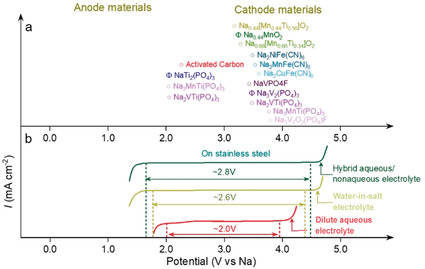
Electrochemical stability windows of aqueous electrolytes and redox potentials of electrode materials in SIBs. (a) Average redox potential of typical anode and cathode materials used in ASIBs referred to the Na+/Na potential scale. (b) Electrochemical stability window of a diluted aqueous electrolyte (1 m Na2SO4, red curve), a concentrated electrolyte (9.26 m NaOTf in H2O water‐in‐salt electrolyte, green curve) and a hybrid aqueous/nonaqueous electrolyte (7.5 m NaOTf in H2O/PC, blue curve), all measured on stainless steel electrodes.
Thus, WiSEs have also been employed for ASIBs. The 9.26 m solution of sodium trifluoromethanesulfonate (NaOTf) in water was shown to offer an ESW larger than 2.5 V (Figure 10). [68] Using such a WiSE, the NaTi2(PO4)3//Na0.66[Mn0.66Ti0.34]O2 cells exhibited superior performance, with high Coulombic efficiency at low rate (91.2 % at the 1st cycle) and excellent cycling stability at high rate (0.086 % capacity fade per cycle). However, the delivered capacity was still far away from the theoretically expected value, while the estimated energy density at a cell‐level is only 20 Wh kg−1. Moreover, the performance of a symmetric aqueous Na‐ion cell, Na2TiV(PO4)3//Na2TiV(PO4)3, employing NASICON electrodes and various concentrated electrolytes has been reported. [69] It was found that the use of highly concentrated electrolytes (both NaClO4 and NaOTf based systems) enabled a stable cycling behavior due to the formation of a resistive but protective interphase layer between the electrode and the electrolyte. However, the OTf‐containing WiSE enabled extremely stable cycling performance at high rate for 1000 cycles without any capacity fading, with higher power performance and lower polarization when compared to the NaClO4 based one.
![(a) Salt to solvent molar and weight ratios for the NaOTf–H2O binary system with corresponding molality. (b, c) Cycle life and low‐rate Coulombic efficiency (0.2 C) of a Na0.66[Mn0.66Ti0.34]O2//NaTi2(PO4)3 full cell in different aqueous electrolytes (NaSiWE: 2 m NaCF3SO3, NaWiSE: 9.26 m NaCF3SO3 and 1 m Na2SO4). Adapted from Ref. [68].](/dataresources/secured/content-1765840379248-02c13031-df47-4fd4-bf05-763983f4e76b/assets/ANIE-60-598-g013.jpg)
(a) Salt to solvent molar and weight ratios for the NaOTf–H2O binary system with corresponding molality. (b, c) Cycle life and low‐rate Coulombic efficiency (0.2 C) of a Na0.66[Mn0.66Ti0.34]O2//NaTi2(PO4)3 full cell in different aqueous electrolytes (NaSiWE: 2 m NaCF3SO3, NaWiSE: 9.26 m NaCF3SO3 and 1 m Na2SO4). Adapted from Ref. [68].
Due to the lower charge density of Na+ ions compared to Li+ ions, a higher Na‐salt concentration is required to compensate for the weaker interaction with the solvent in order to widen the ESW of the electrolyte. [68] Inspired by the results from using LiTFSI‐based aqueous electrolyte, sodium bis(trifluoromethanesulfonyl)imide (NaTFSI) was also explored as salt for aqueous Na‐based electrolytes. [70] Although the lower charge density of the cation contributes to a lower hydration leading to a lower solubility of NaTFSI, the NaTFSI‐based WiSE at 8 m, i.e., close to the solubility limit, exhibited an ESW of 1.8 V and a conductivity of 39 mS cm−1. Sodium bis(fluorosulfonyl)imide (NaFSI) presents a very high solubility in water providing an ESW up to 2.6 V. In principle the use of FSI‐based WiSE could enable the fabrication of high‐voltage ASIBs, however, further studies on the stability of the FSI− anion in water are necessary. [71]
The hybridization approach, widely used for WiSE‐based ALIBs, has also been proposed for ASIBs. Similarly, an aqueous/nonaqueous hybrid electrolyte has been reported, which is based on the use of NaOTf in a mixture of water and an organic solvent, i.e., 7 m NaOTf in water and 8 m NaOTf in propylene carbonate (PC). This hybrid electrolyte offered an ESW extended to 2.8 V, and high ionic conductivity of 25 mS cm−1 at 20 °C. [72] In spite of such a wide ESW, the employed cathode, i.e., Na3V2(PO4)3, suffered from severe degradation (material dissolution) in aqueous electrolyte, reached an initial Coulombic efficiency as high as 79 % and an energy density of 45 Wh kgelectrodes −1 coupled with NaTi2(PO4)3 anode, much higher than those achieved with 9.26 m NaOTf WiSE.
Fluorine‐free WiSEs based on sodium acetate (NaAc) and potassium acetate (KAc) have also been investigated for application in ASIBs. [73] The 32 m KAc + 8 m NaAc hydrate melt electrolyte provided a large ESW and high compatibility with the Al current collector, enabling the successful operation of a NaTi2(PO4)3//Na2MnFe(CN)6 full cell. This electrolyte certainly represents a greener and low‐cost promising alternative to OTf‐based WiSEs.
Compared with Li system, the Na‐based SEI is expected to be less stable because most of the sodium salts (NaF, Na2CO3, etc.) are more soluble in water than their lithium analogues. [74] Moreover, Na‐based electrode materials present lower stability in aqueous electrolytes, most likely due to their solubility, as in the case of Na3V2(PO4)3. Further understanding is necessary to achieve performance requirements for stationary storage application, however, research efforts should be devoted to ASIBs, since they represent the most promising technology for large‐scale energy storage, benefiting from the sustainability, low‐cost and abundance of the raw materials employed.
Zn‐Based Aqueous Batteries: Improving the Stripping/Plating Reversibility
Metallic zinc is an extremely appealing anode material for aqueous batteries, due to its low redox potential (−0.76 V vs. SHE), high theoretical specific capacity (5854 mAh cm−3 and 820 mAh g−1), and stability in water (due to the high overpotential of the hydrogen evolution reaction). [75] The most commonly investigated cathodes, e.g., polyanionic compounds, [76] Prussian blue analogues, [77] manganese‐based oxides, [78] and vanadium‐based oxides, [79] are fully compatible with diluted Zn2+‐containing electrolytes, such as 1 m ZnSO4 or ZnOTf2. However, the cycling performance of aqueous Zn‐batteries is still not satisfactory for practical applications, being hindered by the inefficient Zn metal stripping–plating and the parasitic reactions affecting the stability of the various cathode materials. [80]
While materials development and optimization strategies have already been reviewed in detail,[ 8 , 14b , 81 ] this section mainly focusses on the latest advances regarding the Zn metal stripping–plating improvement. As earlier discussed, the salt's anion strongly affects the cycling behaviour of Zn metal aqueous cells. Various salts (including ZnCl2, Zn(NO3)2, ZnSO4, and ZnOTf2) and their influence on the Zn metal stripping‐plating have been investigated in Zn symmetrical cells. [82] By using 1 m solutions, the electrolytes containing ZnSO4 or ZnOTf2 ensured reversible electrochemical deposition/ dissolution of zinc. Wide ESWs (up to 2.3 V vs. Zn2+/Zn) have been identified, whereas the ZnCl2 and Zn(NO3)2 solutions presented narrower ESWs (lower than 1.2 V vs. Zn2+/Zn) and inferior reversibility owing to the instability of the Cl− and NO3 − anions in aqueous solution. These results were in agreement with the cycling performance of Zn–MnO2 and Zn–V2O5 cells employing ZnSO4‐based electrolytes. The use of 3 m ZnOTf2 instead of ZnSO4, improved the reversibility and kinetics of the zinc stripping–plating, granting CEs approaching 100 %. [82] Such a superior electrochemical performance was attributed to the bulky anion structure and the higher salt concentration. While authors emphasized the influence on the solvation structure of the anion, it is still not clarified whether a more stable and F‐containing SEI formed on the surface of zinc could promote the improved reversibility of the zinc stripping–plating process. In fact, it has been reported that the 0.3 m Zn(TFSI)2 aqueous electrolyte also leads to a better cycling behaviour of Zn‐layered iron vanadate cells in comparison with 1 m ZnSO4 aqueous solution. [83] Practically, using ZnOTf2 as the electrolyte, highly stable Zn//ZnMn2O4 cells have been realized exhibiting a capacity retention of 94 % over 500 cycles at high rate (500 mA g−1). [82] ZnOTf2‐based electrolytes were also found to be compatible with vanadium‐based oxides and polyanionic compounds. For example, cells made of Zn metal anode, CaV6O16⋅3 H2O cathodes and 3 m ZnOTf2 aqueous electrolyte have shown superior electrochemical performance. [84] Presently, ZnSO4‐ and ZnOTf2‐based electrolytes are the most commonly used electrolytes in aqueous zinc batteries. Nevertheless, due to the limited solubility of these two salts, free water is still available in the corresponding electrolytes, thus limiting their ESW. [82]
In 2018, the bi‐salt Zn(TFSI)2–LiTFSI aqueous electrolyte was proposed for aqueous Zn metal batteries. [36] The concentration of Zn(TFSI)2 was fixed to 1 m, while the concentration of LiTFSI varied from 5 to 10, 15, and 20 m. With increasing concentration of LiTFSI, the efficiency of the Zn stripping and plating remarkably improved. Indeed, dendrite‐free Zn plating–stripping (with a nearly 100 % CE) was achieved when using the 1 m Zn(TFSI)2 + 20 m LiTFSI electrolyte. This enabled the realization of a Zn–LiMn2O4 hybrid battery characterized by an impressive long‐term stability, i.e., the capacity retention was 85 % after 4000 cycles, and a limited supply of zinc anode (Zn: LiMn2O4 mass ratio of 0.8:1), as shown in Figure 11. Further structural and spectroscopic studies combined with molecular‐scale modelling revealed that the high population of anions in the vicinity of Zn2+ induces the formation of close ion pairs (Zn–TFSI)+ and suppress the presence of (Zn(H2O)6)2+. The ion pairs hinder the H2 evolution and promotes a dendrite‐free, highly reversible Zn plating–stripping. Similarly, a promising plating–stripping efficiency was also detected for the low‐cost 0.4 m ZnOTf2 + 8 m NaClO4 electrolyte. [85] Nevertheless, it should be noted that when using the 1 m Zn(TFSI)2 + 20 m LiTFSI electrolyte, the cation intercalated into the cathode is mainly Li+ rather than Zn2+, which result in a relative lower specific capacity because of the electrolyte being an active cell component. Mixed salts concentrated electrolytes of 1 m ZnOTf2 + 21 m LiTFSI were also investigated using a V2O5 electrode. [86] It was found that the highly concentrated LiTFSI electrolyte induced a decrease of the specific capacity from 350 to 250 mAh g−1 measured at 50 mA g−1, but significantly enhanced the cycling performance. Ex situ and in situ studies proved that the intercalation/de‐intercalation of Li+ played a significant role in the cells employing the mixed salts electrolyte.
![(a) Galvanostatic Zn stripping/plating in a Zn//Zn symmetrical cell at 0.2 mA cm−2. (b) SEM image and XRD pattern (inset) of a Zn anode after 500 stripping/plating cycles in the highly concentrated Zn‐ion electrolyte (HCZE, 1 m Zn(TFSI)2 + 20 m LiTFSI). (c) A typical voltage profile of the Zn//LiMn2O4 full cell in HCZE at a constant current (0.2 C; areal capacity of LiMn2O4, 2.4 mAh cm−2). (d) The cycling stability and Coulombic efficiency of the Zn//LiMn2O4 full cell in HCZE at 0.2 C. Adapted from Ref. [36].](/dataresources/secured/content-1765840379248-02c13031-df47-4fd4-bf05-763983f4e76b/assets/ANIE-60-598-g014.jpg)
(a) Galvanostatic Zn stripping/plating in a Zn//Zn symmetrical cell at 0.2 mA cm−2. (b) SEM image and XRD pattern (inset) of a Zn anode after 500 stripping/plating cycles in the highly concentrated Zn‐ion electrolyte (HCZE, 1 m Zn(TFSI)2 + 20 m LiTFSI). (c) A typical voltage profile of the Zn//LiMn2O4 full cell in HCZE at a constant current (0.2 C; areal capacity of LiMn2O4, 2.4 mAh cm−2). (d) The cycling stability and Coulombic efficiency of the Zn//LiMn2O4 full cell in HCZE at 0.2 C. Adapted from Ref. [36].
These results inspired further research toward a re‐visitation of concentrated Zn‐based aqueous electrolyte. In fact, suppressing the water reactivity with the Zn anode, is fundamental to enable the reversibility of the Zn stripping/plating. With these merits, an eutectic mixture of urea/LiTFSI/Zn(TFSI)2 “water‐in‐DES” electrolyte endows the enhancement of Zn plating/stripping even at low rates. [87] Despite these promising properties, however, the involved mechanism and the correlated Zn/electrolyte interphase still require deeper investigations. Indeed, with a very low cut‐off potential (commonly lower than 0.2 V vs. Zn2+/Zn, equaling to −0.5 V vs. SHE), the occurrence of a surface layer through the reduction of the anion, especially bulk anions like TFSI− and OTf−, cannot be excluded. On the other hand, engineering a multifunctional polymeric interphase appears to be an interesting strategy to regulate the aqueous Zn deposition behavior. Cui et al. designed a “brightener‐inspired” polyamide coating layer allowing the achievement of dendrite‐free Zn deposition with high areal capacity (10 mA h cm−2) for the first time. [88] The influence of WiSEs on the cathode material dissolution and the cathode/electrolyte interface have been scarcely investigated. Despite some stable aqueous Zn batteries based on vanadium oxides have been reported, [89] the severe dissolution in water of these cathode materials still represents an issue to be addressed, especially at low current density when side reactions are more pronounced.
Potassium, Proton, Magnesium, Calcium Aqueous and Aluminium Rechargeable Batteries
Potassium is a relatively abundant element. However, its larger atomic mass and size compared to Li and Na, makes K‐ion batteries (KIBs) less attractive for high energy applications. [90] Nonetheless, aqueous rechargeable batteries based on K+‐shuttle (AKIBs) meet the low‐cost requirement and are a potentially viable technology. [91] Promising electrode materials for AKIBs are the Prussian Blue analogues (PBAs).[ 14c , 92 ] A WiSE based on potassium acetate has been reported for application in AKIBs. [93] The 30 m KAc electrolyte enabled a wide stability window (3.2 V) allowing the reversible operation of KTi2(PO4)3 as anode material. Recently, an AKIB system has been reported, consisting of the Fe‐substituted, Mn‐rich Prussian blue KxFeyMn1−y[Fe(CN)6]w⋅z H2O cathode, the organic 3,4,9,10‐perylenetetracarboxylic diimide anode and the 22 m KOTf WiSE. [94] This AKIB exhibited a high energy density (80 Wh kg−1), well operating in wide rate (0.1–20 C) and temperature (−20 to 60 °C) ranges. Non‐metal cations, e.g., hydronium (H3O+) and ammonium (NH4 +) ions, can also serve as charge carriers in rocking‐chair batteries (see Table 1). For this reason, they have recently attracted great interest. [95] A WiS electrolyte based on 25 m ammonium acetate (AmAc) was reported within an expanded ESW up to 2.95 V. The aqueous rechargeable ammonium battery using titanic acid TiO1.85(OH)0.30⋅0.28 H2O as cathode exhibited a specific capacity of about 84 mAh g−1. [96] These results are encouraging, especially for grid‐scale energy storage application, however, only few studies have been reported up to now, suggesting the need of more research efforts in this direction.
Magnesium‐ion batteries (MIBs), involving a two‐electron redox process, are considered as an attractive alternative chemistry. In fact, aqueous rechargeable magnesium batteries (AMIBs) could, in principle, offer the advantages of high energy density and low cost. [97] Interestingly, Wang et al. proposed a high voltage AMIB using the 4 m Mg(TFSI)2 WiSE offering an extended ESW (2.0 V), i.e., much higher than that obtained using a 1 m MgSO4 electrolyte (≈1.3 V). [98] By coupling such a WiSE with the Li3V2(PO4)3 cathode and the poly pyromellitic dianhydride (PPMDA) anode, 1.9 V AMIBs have been realized exhibiting high specific energy (68 Wh kg−1) and power (1440 W kg−1) densities, and superior cycling stability (over 6000 cycles). These values well match with the requirements for batteries used in commercial grid‐level storage, such as lead acid (75–300 W kg−1) and vanadium redox‐flow batteries (60–100 W kg−1). Ca2+ is another divalent ion that has potential for energy storage application due to its chemical similarity with Mg2+ but faster reaction kinetics (thus better power performance) and lower polarization. [99] The realization of a safe and low‐cost aqueous Ca‐ion battery (ACIB) based on the highly reversible polyimide anode and copper hexacyanoferrate (CuHCF) cathode employing the 2.5 m Ca(NO3)2 aqueous electrolyte has been demonstrated. [100] Jeong et al. investigated the effect of the salt concentration in aqueous electrolyte on the storage performance of Ca2+ ion in CuHCF. [101] The results demonstrated that the use of the 8.37 m Ca(NO3)2 electrolyte improved the discharge capacity and cycle life compared to diluted one (1 m Ca(NO3)2). Rechargeable aqueous Al‐ion batteries (AAIBs), are attracting large attention in view of their fast charging ability, high cyclability and satisfactory capacity conferred by the three‐electron redox process. In addition, aluminium is abundant, and low cost, and presents a high volumetric capacity. [102] Recently, a novel Al/AlCl3/graphite AAIB using a WIS (AlCl3⋅6 H2O) electrolyte exhibited an average discharge voltage of 1.44 V and a discharge capacity of 165 mAh g−1 with a high coulombic efficiency exceeding 95 % after 1000 cycles. [103]
Despite the promising properties, the key challenges for multivalent systems are the development of innovative compatible electrolyte systems and the poor Al3+ mobility in many electrolytes and positive electrodes.
Conclusions and Outlook
Advances in aqueous batteries are strongly related to innovations at the electrolyte side. Concentrated electrolytes, characterized by a unique electrochemistry, will play a crucial role in the development of high‐energy ARBs, eventually enabling long cycling life. Their use enables a wider electrochemical stability window, thus increasing the average cell voltage. In addition, the formation of a stable SEI formation prevents the exposure of electrode materials to electrolytes, thus also limiting parasitic reactions and dissolution processes typically occurring when using NASICON‐based electrodes.
However, although great progresses on the performance of aqueous batteries using concentrated electrolytes have been obtained, still some main challenges need to be faced. An important and urgent challenge is to reduce the cost of the already existing concentrated aqueous electrolytes, such as the sulfonate‐based electrolytes, to strongly decrease the overall cost at the cell level. Due to the very large amount of salt used, the cost of the electrolyte, in fact, will strongly depend on the cost of the employed salt. In addition, the density represents another important parameter. Indeed, the high density of concentrated electrolytes will inevitably lead to a decreased specific energy of the cell when considering equal volumetric amounts of liquid in the cell. ARLIBs are widely investigated due to the superior technological readiness level of the non‐aqueous systems and large number of available electrode candidates. On the other hand, the low‐cost philosophy of the sodium‐ion technology perfectly matches the idea of aqueous based electrolytes, further reducing the costs, thus representing the most promising next generation sustainable storage system. While cost reduction is directly associate to manufacturing improvement, performance improvement is more challenging. In particular, extra efforts should be addressed in the search of suitable electrode materials obtained from low‐cost and abundant raw materials and high performance for application in large‐scale energy storage applications.
Nonetheless, electrode materials need also to be optimized with respect to the use of WiSEs. One of the biggest challenges in the design of improved electrode materials, is their chemical stability (including solubility) into the aqueous electrolytes, most likely associated to the highly dipolar nature of water. Although concentrated electrolytes are capable to improve the cell voltage, the existing aqueous technologies still remain at a benchmarking level, highlighting the need of further improvement to compete with lead–acid batteries.
Another crucial phenomenon to be elucidated and investigated is the SEI formation in concentrated electrolytes. The fundamental understanding of the charge‐transfer processes and storage in ARBs is essential for a rational design of the next generation battery components, thus enabling the obtainment of high‐performance systems. The identification of the fundamental components that underlie the functions and formation mechanism of the new anion‐derived SEI chemistry may represent the key turning point for a technological breakthrough. Given the complexity of the SEI nature, a variety of techniques need to be used to simultaneously achieve the chemical, morphological, temporal and spatial sensitivity required to understand all its aspects.
Currently, most reports on surface characterization is performed via post‐mortem X‐ray photoelectron spectroscopy, Fourier transform infrared spectroscopy, scanning electron microscopy and transmission electron microscopy. However, sample handling, air exposure, or beam damages cannot be excluded and the SEI nature may change respect to its original composition or morphology formed within the cells. For instance, it is known that residual LiTFSI or LiFSI salt on the electrodes’ surface can undergo decomposition into LiF by X‐ray radiation or Ar+ sputtering exposure in an X‐ray photoelectron spectroscopy chamber. [104] Thus, in situ or operando analyses play an important role for the obtainment of more accurate information on interfacial chemistry. [105] There is no doubt that all cell components play a fundamental role in a battery chemistry, however, electrolytes represent the most crucial one, being the mean through which the electrodes communicate. The impact of salt concentration into the chemistry of aqueous electrolytes, is an important scientific knowledge not only for metal‐ and metal‐ion‐ based electrode chemistries, but offers suggestions also for other energy storage systems such as redox flow batteries (RFBs) [106] and dual‐ion batteries (DIBs). [107]
Overall, as shown in this review, the gained knowledge on the chemistry of concentrated aqueous electrolytes for application in high‐energy rechargeable batteries can provide the basis for the development of a wide range of advanced future aqueous energy storage technologies.
Conflict of interest
The authors declare no conflict of interest.
Biographical Information
Huang Zhang is an Associate Professor in the Institute of Flexible Electronics, Northwestern Polytechnical University. He received his Ph.D. degree in Physical Chemistry from Karlsruhe Institute of Technology in 2018. His current research interests are focused on the development of advanced electrode and electrolyte materials for batteries.

Biographical Information
Ivana Hasa is a Research Scientist at Karlsruhe Institute of Technology, Helmholtz Institute Ulm (Germany). She received her PhD in chemistry at Sapienza University of Rome (Italy). Before joining Helmholtz Institute Ulm, she was a chemist postdoctoral fellow at Lawrence Berkeley National Laboratory (USA) in the group of Dr. Robert Kostecki. Her current research activities are focused on the design of functional materials and the understanding of the processes governing the chemistry of sodium‐ion batteries.

Biographical Information
Stefano Passerini is Professor at the Karlsruhe Institute of Technology, Helmholtz Institute Ulm. Formerly Professor at the University of Muenster, he co‐founded the MEET battery research centre at the University of Muenster. His research activities are focused on electrochemical energy storage with special focus on improving the sustainability of high‐energy batteries.

Acknowledgements
The authors would like to acknowledge the support of the Helmholtz Association within the Network of Excellence on post‐Lithium batteries (ExNet‐0035). H.Z. acknowledges the financial support from the Fundamental Research Funds for the Central Universities. Open access funding enabled and organized by Projekt DEAL.
References
2
3
4
4a
4b
5
7
9
10
11
12
13
13a
13b
14
14a
14e
14e
15
15a
15b
15c
16
17
18
19
20
20a
20c
21
21a
21b
21c
21d
22
23
23a
23b
23c
23d
23e
23f
24
24a
24b
24c
26
27
28
30
31
32
33
34
35
36
37
38
39
40
41
42
43
45
45
46
47
48
49
52
52a
53
54
55
56
57
58
59
60
61
62
63
63a
63b
64
64b
65
65a
65b
66
67
67a
67b
68
69
70
71
72
74
75
75a
75b
76
78
79
80
80a
80b
81
81a
81b
82
83
84
85
86
87
88
89
89
90
90a
90b
91
92
93
94
95
95a
95a
95b
95b
96
97
97a
97b
98
100
101
102
103
104
105
106
107
107a
107b